|
7587 Install and HMM
(individual files in ZIP) 586VE SBC
Information (GR6C06.pdf) IBM SBC 586VE sbc113a.zip SBC Flash
Update from Radisys! sbc111.exe SBC Flash Update (511,000 bytes , 8-15-00) sbc110.exe SBC Flash Update(430,000 bytes 5-15-00) 47L2629.exe Diagnostics (924,000 bytes, 10-4-99) SBCV video
drivers link to SiS website. SiS_900_sl119.zip v1.19 SiS 900 drivers SiS 6801 Super I/O FDC, Parallel, Serial, FIR Common pin-compatible replacement is the ITE 8661 Datasheet Common hit while searching - "Super-I/O ITE 8661/SiS 6801 rev 2 found at port 279h" IBM 586VE 47L2387 
— SBC automatically adjusts processor core-voltage during POST – Pentium up to 200 MHz – Pentium with MMX up to 233 MHz – AMD K6-2 or K6-3 up to 500 MHz DIMMs Min 32MB, max 384MB. Two 168-pin DIMM sockets (Bank 0 and 1). Gold-tabbed, non-parity, synchronous-DRAM DIMMs. 32, 64, 128, or 256 MB. The DIMMs do not have to be the same size; the SBC will optimize for the maximum performance of each DIMM. NOTE: Max RAM is (1) 128MB DIMM and (1) 256MB DIMM. 47L2707 32 MB DIMM, 10-ns, non-parity, gold tab 47L2708 64 MB DIMM, 10-ns, non-parity, gold tab 47L2709 128 MB DIMM, 10-ns, non-parity, gold tab 47L2744 256 MB DIMM, 10-ns, non-parity, gold tab L2 Cache The SBC has a 512 KB level-2 (L2) cache, which cannot be upgraded. J41, 42 12Mbit/s USB 1.0 ports
Group A Connectors 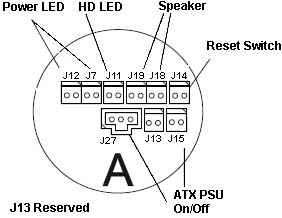 J12, J7 Power-On LED (green LED) Turns on whenever 5 volts is applied. Two 2-pin connectors operate as a single connector. The pair supports the IBM 2-pin LED connector and the industry-standard 3-pin LED connector. The 2-pin power LED can connect to J12 or J7. The 3-pin power LED can be connected across J12-1 and J7-1, or across J12-2 and J7-2. 
J11 HD Access LED (yellow LED) It lights for activity on either IDE port. 2-pin header connects to HD-Access LED.
J14 Reset Switch Short both pins together or use a system reset switch to perform a hardware reset.
J19, J18 Speaker This consists of two 2-pin connectors. They can drive a speaker or a speaker LED (in noisy environments). A standard 8-ohm speaker can be connected to give normal audio outputs. The two connectors act as a single header and supports a IBM 2-pin speaker connector or the industry-standard 4-pin connector. The 2-pin speaker cable connects to either J19 or J18. The 4-pin cable connects across both J18 and J19 (the two outer-most pins are used). 
J15, J27 ATX Power Supply Used with soft on/off control of an ATX power supply. It uses a momentary-make on/off switch connected to the SBC instead of the standard two-pole switch connected to the power supply. As a result, the SBC controls the on/off state of the power supply. When using the soft on/off control, connect a momentary-make on/off switch to the 2-pin connector (J15), and connect the 3-pin auxiliary power-supply cable to the 3-pin connector (J27). Note: Use only a momentary-make switch and a properly-wired power supply. J15 Pinout
J27 Pinout
Group B Connectors 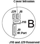 J9 Infrared Port This is a 5-pin, 2-millimeter, center-line connector. It is configured as a serial port and supports slow IR (SIR) and amplitude-shift keying IR (ASKIR) standards.
J8 Cover Intrusion Port Standard 2-pin, 2-mm, center-line connector. It is routed to the cover intrusion detector
The logic on the SBC works as follows: The two connector pins on the SBC are routed to the detector circuitry. When the pins are shorted, an event is latched in the detector. The event is latched even if the computer is turned off or the power cord is unplugged. Bit 6 at I/O address 0158h contains the status of the latch. If bit 6 is 1, the latch has been tripped. The latch is reset by setting bit 6 at I/O address 0157h to 1. To use the logic to detect a cover being removed, the user must connect a switch that is closed when the cover is removed, and open when the cover is installed. Clear Password Removing Power-on or System Administrator Password: 1. Turn off computer and remove cover. 2. Short both pads on password clear pad for 10 seconds -OR- remove battery for 10 minutes. 3. Reinstall cover. 4. Turn on computer and run Configuration/Setup Utility program. 5. If a password is required, you must enter a new one. Switch Block 1 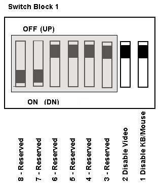 8 - 3 Reserved Leave these alone. 2 Disable Video Switch 2 lets you disable the SBC video function. When SW2 is down (on), it disables all video drivers on the SBC. Default is video enabled (off). Disable Keyboard/Mouse SW1 disables keyboard and mouse ports. Default position is keyboard and mouse ports enabled (off). Switch Block 2 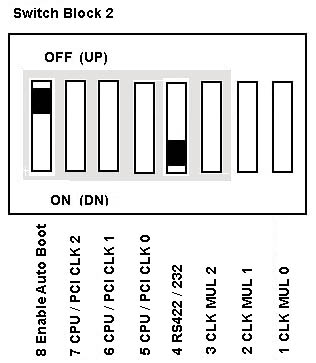 8 Enable Auto Boot Switch 8 controls auto-boot feature at power-on. Auto Boot detects configuration errors at power-on and automatically alters CMOS settings to match hardware so computer completes boot process without operator intervention. Use this carefully because it can mask hardware problems. Hardware errors could cause the computer to change configuration and possibly lead to inconsistencies in the operation of hardware and applications running on the computer. Default is auto boot disabled (off). 4 RS-422/485 or RS-232 Switch 4 controls serial port B electrical interface. If SW4 is up (off), it is RS-422/485. If SW4 is down (on), it is RS-232. The default is RS-232 (on). Internal Processor Clock Multiplier Switches (Switch Block 2, SW1-3) Switch block 2 is used to configure the SBC to CPU speed. SW1-3 select the CPU internal clock multiplier. SW5-7 select input frequency and external bus speed.
Input Frequency / External Bus Clocking (Switch Block 2, SW5-7 ) Optimal settings for each CPU-input frequency between CPU, PCI bus, and host bus.
Processor Voltage Selection When turned on, the SBC automatically selects correct core voltage.
76H4385 Remote-IPL chip (for SBC with Ethernet only)
|
||||||||||||||||||||||||||||||||||||||||||||||||||||||||||||||||||||||||||||||||||||||||||||||||||||||||||||||||||||||||||||||||||||||||||||||||||||||||||||||||||||||||||||||||||||||||||||||||||||||||||||||||||||||||||||||||||||||||