|
Intelligent Disk Controller 195295fm.exe
Server 195/295 Field Maint. Test 2.0 IDC Board
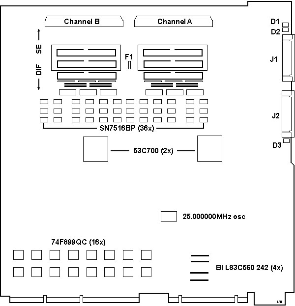
Channel A and B
outlines only. For some odd reason, the HPDB-50 ports have the usual catches for a HPDB-50 SCSI cable to latch on to. But oddly enough, there are short hex mounting posts, similar to those used with parallel or serial ports. These hex posts are right up against the HPDB-50 port catches, and would prevent anyone from using the pretty good cable connectors that clip on to the SCSI port. 3 Extra 74F899QC? Select SE or Differential with
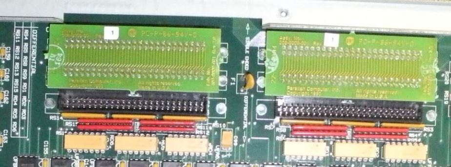
PCBs Note the silkscreened "Single Ended" and "Differential"
between the 50 pin headers. This image shows the configuration for SE drives. Now, I am familiar with the term pack on a SCSI/A
needing to be removed if there are SCSI devices on the
External -AND- Internal ports. So how does one remove
the term resistors in this case? Some fiddly bit of work
pulling these SIPPs out, quite cramped if you want to
pull the three SE SIPPs out... SE and Differential
Terminators 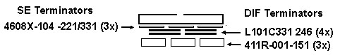 SE and Diff Terminating
Resistor Identities NOTE: Pin 1 on the
SIPPs and DIPs are to the right! Disk/Controllers/Bays:
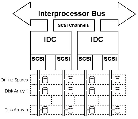
To run Orthogonal RAID, you need two IDCs, so there are
four NCR 53C700 (2 per IDC). Both 53C700s on an IDC are
fed from a 25.000000 MHz oscillator. No fooling, six
places to the right. With normal RAID, all of the drives
are on one controller, (all use one clock), but 2
independent IDCs NEED a very precise clock on-board to
enable them to synchronize. NOTE: The 53C700
has a "SCRIPTS" processor, which is the "RISC-based"
controller. There is no separate RISC chip on the IDC. "Factory" disks are the IBM 0661-467 (400 MB) and 0663
(1 GB) SCSI disks. The 295 does check the HD firmware
for a text string. Supports 1 to 28 hot insertion/extraction disks (all
hot pluggable). The removable trays are CRU DataPort I trays, which are
on Flea-Buy... Max of 9 GB internally (9 bays x 1 GB disk). Max of 28 GB total (4 ) 53C700 x 7 disks (1GB) with
Exp Cabinets. Ten 3.5" half height bays internally (diskette uses
one). That leaves 9 bays, with one for the system
disk, leaves 8 drive bays to support Orthogonal RAID-5
(with on-line spares). So without the SCSI expansion
chassis, this limits one to 8 drives (two SCSI drives
connected to each 53C700). I suppose you could run one
SCSI drive on each 53C700 for the smallest OR-5
footprint, but you won't have the on-line spares to
support automatic RAID array rebuilding... Supports 1 to 3 optional External Expansion Cabinets
each with ten 5.25" half height or five 5.25" full
height bays. OS/2 preload includes FTUTIL: allows disk pairs to be
striped, mirrored, or duplexed. Also allows hot spare
pooling, hot insertion/extraction, automatic data
rebuild, and hot fix.
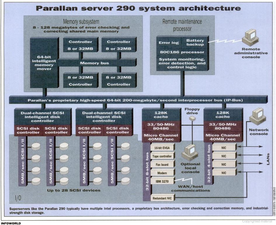
One or two disk controllers can be
installed on the IP-Bus, providing two or four SCSI disk
channels, respectively. Each channel can support up to
seven SCSI disks, for a maximum of 28 disk drives.
PDAs are set up using the Server 295 reference
diskette. Information on the PDAs can be displayed
using MASS/2. Configuring spare drives and
reconstructing a PDA following a drive failure is done
using the utility PDAUTIL, as well as automatically by
MASS/2, if there is a hot-standby spare disk in the
system. Orthogonal RAID-5
Multiple requests to one disk or across one adapter
will typically take longer to satisfy than the same
number of requests to multiple disks across multiple
adapters. A standard RAID-5 system depends on just one
disk adapter which all of the disks are connected. RAID Level Performance Characteristics
Note 2 : Availability = MTBF of one disk divided by the number of disks in the array. MASS/2 Features
(Maximum Availability and Support System/2) Integrated software allowing monitoring, controlling,
tuning, and recovery of 295. Allows 295 to be
geographically distributed while permitting
comprehensive, centralized control with mainframe-like
remote administration. Features: Continual monitoring of CPU, memory, disk,
network, and swapping level utilization via realtime bar
graph, and 1 hour history in RMP RAM, and historic logs
on disk. Continual monitoring of temp, PSU voltage,
single bit memory errors, network errors. Comprehensive configuration details (processors,
memory, SCSI, arrays, spares, RMP, UPS status,
adapters). Alarm and threshold selection with automatic
dial out capability for various events like disk
failure, disk full, reboots, shut downs, memory errors,
over temperature, power low/high, and network errors. Scheduled power down and power up; remote
rebooting. SAA-compliant graphical user interface
(hierarchical). Access to network operating system logs and
server logs. Multilevel password based security; G File
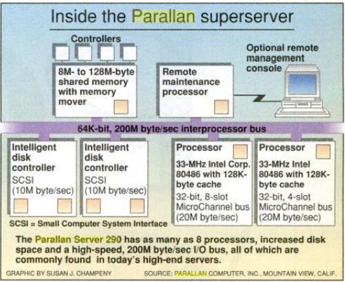
transfer capability. Preinstalled on Server 295. Inside the Parallan Super
Server Parallan Server 290
Architecture |