|
Common to 195 and 295 8600 Power (Todd Products MAX-753-0512) MAX 700/750 Series Datasheet MAX-754 Series Datasheet (Replacement) I do not have a complete list of Todd MAX-70x/75x and
NMX- supply models. Others may be compatible, but I
can't prove it. One plus is that the case fan is
connected to leads on TB2, so you can swap a fan-cover
onto a suitable replacement PSU... 750 watt universal power supply; Optional
redundant power supply. NOTE: The PSU is
Universal, but NOT Auto-Ranging. There is a set of spade
terminals on the PSU's PCB, connected for 115v, open for
230v. Replacements for MAX-753-0512 MAX-754-1205P has an NSN of 6130-01-487-6246. Unfortunately, all I see is "RFQ" for price. Spidey sense makes me think that it isn't cheap... Some Wild
Guesses
NOTE: The MAX-70x
models Output #1 is +5V @ 100A,
useable BUT will support less MCA adapters or hard
drives or memory. Only a 100w difference, so if you
are thoughtful, it should work. NOTE: All Output #2 outputs have a sustained / peak rating of 12A / 20A. (peak) refers to a momentary surge, say for starting drives. Inrush current. So, +12v at 12A sustained, +12v at 20A for a short period... CAUTION!
MAX-754-1252 Output #3 is -5.2V @ 10A, NOT -12v!!! Will
not function as a replacement... MAX-753-0512 Fan
25.4mm thick, 92mm square MAX-753-0512 Terminals
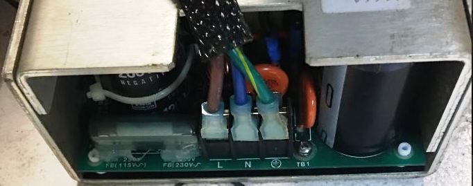
TB1
Terminals (AC
Input)
NOTE: inputs TB1-3
use a Barrier strip with #6-32 screws on 3/8”
centers Lorenzo
Mollicone says: Input Select: pair of 1/4" spade terminals mounted on PCB, up from TB1 underneath the cover. For 115v, connect with a short wire with female spade connectors, or for 230v, leave the terminals bare (open). NOTE: The Input
Select jumper wire is a heavier gage. Checking. TB2 Terminals (DC Output) 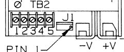
NOTE: Output #1 (-V and +V) is connected with Bus bars using #1/4-20 screws NOTE: Outputs # 2-4 use a Barrier strip with #6-32 screws on 3/8” centers NOTE: Cover fan connects to TB2. Fan Black goes to TB2-5, Fan Red goes to TB2-4. J1 Terminals (Status and Control), That little plastic 4 position plug to the right of TB2. Pin numbering is reverse of TB2, Pin 1 on right, pin 4 on left. Go figure...
J1 Connector AMP MTA type #640456-4 pin header (locking) NOTE: Pin 3 (AC Fail or DC Good) is not connected (N/C). There is no wire to Pin 3. If you are replacing the original MAX-753-0512 with a PSU that has PF, leave the PF unconnected. MAX-753 Series Specs: OUTPUT Adjustability: User adjustable ±5% minimum. Line & Load Reg: ±1% over AC range, 0-100% load change. NOTE: Output #1 requires min load of 10%. Ripple & Noise: < 1% p-p or 100 mV, whichever is greater. Remote Sense (Output #1): Corrects for 250 mV total line drop. Open sense lead protection. Temperature Coefficient: 0.02% per degree C. Stability: 0.1% over 8 hours after 30 minutes warm-up. Transient Response (Output #1): Output v returns w/in 1% < 500 μs for 50% load change. Peak Transient Does not exceed 5%. Overload: All outputs overload / short circuit protected. Auto recovery upon fault removal. Overvoltage (Output #1): Protects load against power supply induced overvoltage. Trip point factory set so output voltage cannot exceed 136% of nominal. Remote Inhibit: Contact closure to negative sense line drops output power to nominal OPTIONS: Option “A”, AC Auto-Range: Automatically selects 115 or 230 Vac range. Option “F”, Fan/Cover Assembly: Cover w/ fan needed for full ratings at 50°C ambient. Option “G”, DC Power Good: Not present on 295. Option “P”, AC Power Fail: Not present on 295. |