|
Model 95 XP486 Technical Reference SHS15F2246 IBM PS/2 Model 95 XP 486 HMR SHS85F1676 IBM PS/2 Model 95 XP 486 HMS 
DS1210 Nonvolatile Controller Chip - Converts CMOS RAMs into nonvolatile memories Dallas DS1285 Real Time Clock Datasheet [1 page] DS1285 DS1285 '93 [4 pages] DS1287 Datasheet [used to describe D1285 pins, 17 pages] SRM2264LC12 Datasheet Standard SRAM, 8KX8, 120ns, CMOS, PDIP28 BH1 - Common CR2032 Lithium coin cell with a normal life expectancy of five to seven years. Battery life is directly related to how much the machine is used, since the battery is used only when the system is powered off. For correct machine operation, battery voltage should be between 2.5 volts and 3.7 volts. NOTE: Low voltages can corrupt CMOS bits. To check the battery voltage:
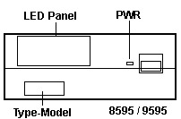
- Turn Off System Unit Power If battery voltage drops below 2.5 volts, replaced it with a CR2032. After replacing battery, power on, check configuration, and check for proper operation. SIMM Connector Versions [Grey or Green] 8MB ECC SIMMs from IBM (Option P/N 92G7208, FRU P/N 92F0098) may not fit properly in the SIMM connectors of some systems. The following system types and models are potentially affected. 8595 - All models 9595 - model 0LF (See note below) Early production 8595 system boards have gray plastic SIMM connectors which physically interfere with the installation of the referenced 8MB ECC SIMM. Later production system boards used a green SIMM connector, which is compatible with the larger SIMMs. Many earlier systems, which have been serviced in the past 18 months, could have the later production system board (green SIMM connectors) already installed. All system boards with green memory SIMM connectors, regardless of model number or processor upgrade are not affected. NOTE: 9595 model 0LF is the only model of 9595 to use the 8595 system board, FRU P/N 92F0270, (identified by a single serial and a single parallel port). 8595/9595 Ports
DB25 Serial Port  DB25 Serial Port Pinout
8595 / 9595 Parallel Port  J4 There is no official name, but... Jim Shorney Jim, I followed that pin out a while back. So it goes to remote power on. OK. What, praytell, is the importance of your find? Tim Clarke Um, hadn't thought of that... The parallel port is NOT ExpressPrint capable... From the Godfather-
For information again: The "small" 9595s model -xLx (Type 2) and -xMx (Type 3) had the old planar - all others usually had the 9595A-planar (Type 4 -xNx, -xPx, -xQx). Editor's Note: Checked a -xKx and -xMx planar. Same chipset, same oscillator values. Only difference was some SMD oscillators replaced metal ones. A few less logic chips. And the -xLx, -xMx planars are a lovely green. |
||||||||||||||||||||||||||||||||||||||||||||||||||||||||||||||||