ADTRON SDDS
SDDS Summary SDDS Specifications
SDDS Installation Manual
ADTRON PC CARD Image Transfer Utility
SDDS-04A Removable tape emulation
NOTE: W98SE automatically detects SDDS-04A [ID2], installs the driver for it [generic tape?], and it shows up as a tape controller under Device Manager, "ADTRON SDDS N18012" firmware "2h6f".
Did a test backup of a sub-dir using Micro$oft Backup, and it is wicked-fast! Used a 256MB CF card, so NO moving parts...
BUT... it does NOT show up under File Manager, or whatever W98SE calls it...
BTW, it really is different, the BT-646 splash screen at POST shows eight instances of ADTRON SDDS N18012 firmware 2h6f, 2-0 through 2-7... Still, there is NO confusion of any kind when accessing the SDDS-04A, even with multiple LUNs...
One Type II PC Card slot, 3.5-inch tape drive bay mounting, 4" x 1.625" tall. The mounting holes in the PCB do NOT line up with the floppy mounting holes, so you will need the ADTRON mount...
PCB is marked "SCSI SDDS-XXA" so my guess is the 01A / 03A / and 04A PCBs are identical, save the shunts or jumper header presence or absence...
Supports Active Termination, TERMPWR, SCSI Disconnect, SCSI Parity
Cirrus Logic CL-PD6720-QC-B ISA–to–PC-Card Host Adapter Preliminary Data Sheet
AMD AM186ER-40KC Hi-Perf, 80C186-Compatible, 16-Bit Embedded MPU w/ RAM
Making the Most of the Am186ER or Am188ER Microcontroller
AMD AM53CF96KC Enhanced SCSI-2 Controller (ESC)
The Am53CF96 can be configured as single ended or differential.
Dallas DS21S07A SCSI Terminator Single Ended, thankfully....
SDDS-04A
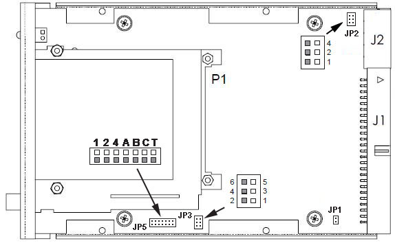
JP1: SCSI Termination Disable
On-board active SCSI termination is enabled by default. Disable it by jumpering JP1
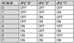
JP2: SCSI ID
SCSI ID is set by jumpers on pins 4, 2, and 1. By default, the SDDS SCSI ID is set to 2.
JP3: Option Jumpers
Pins 5-6 Disable SCSI Disconnections SCSI disconnects are controlled by the SCSI
host adapter. Disconnects are enabled by default on this product. Without using the host adapter controls, disconnects can be disabled by installing a jumper on pins 5 and 6
Pins 3-4 Gang Sockets Only PCB holes, not supported on SDDS-04A
Pins 1-2 Swap Sockets Wire shunt on SDDS-04A.This option is only available on the SDDS-01A; other models will have the settings fixed, and should not be modified.
JP5: Combination of JP1, JP2, and JP3. Nothing but through holes on SDDS-04A.
1,2,4 Sets SCSI ID
A,B,C Swap, Gang, SCSI Disconnect
T [actually TD] Termination Disable
LED Status Indicator (bi-color - Green/Red )
When power is first applied, the SDDS performs a self-test. The LED flashes Green-Red twice. After the self-test, the LEDs remain off until a card is inserted.
|
LED |
Description |
|
Solid Green |
Card power is ON |
|
Flashing Green |
Error – Card not
recognized |
|
Solid
Red/Flashing Red |
Host
accessing |