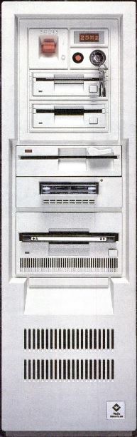
CompuStar 100
All this AND a nice 8580-style handle!High-Tech
Computing, Cafeteria Style Byte Magazine
Vol 14 No. 04, April 1988, Mark L. Van Name Pages
182-184, 182-184
Advertising, Byte Magazine Vol 14 No 05, May 1989 page 23
US 4971563 - Modular Backplane Assemblies for Computers
Advertising, Byte Magazine Vol 14 No 05, May 1989 page 23
US 4971563 - Modular Backplane Assemblies for Computers
This stuff is mostly on the 80286
version...
Looks familiar... Is it a Dell???
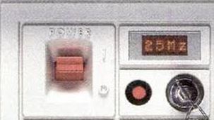
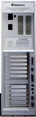
Power switch, a reset button, a front panel lock, and a four-character LED display. The LED shows both diagnostic and system status information. For example, "R" when reading the hard disk and "W" when writing to the disk. If you press the Control or Shift keys, the LED shows the current system speed.
You control the 80286 CPU Board speed with the Ctrl/ Alt/ + combination to raise the speed, or Ctrl/ Alt/ - to lower it. The system beeps once each time you lower its speed, and twice each time you raise the speed. You can also use a Wells utility, SPEED.EXE, to set the speed from the DOS command line."
On the standard setup disk are DISP.EXE and SCROLL.EXE, with which you can display four characters of your choice, either statically or scrolling from right to left, in the LED display. The Wells American ROM BIOS was the CompuStar Multi-Processor Convertible Microcomputer V l .05 BIOS ." [ed. which might be an AMI based BIOS]
Looks familiar... Is it a Dell???
Power switch, a reset button, a front panel lock, and a four-character LED display. The LED shows both diagnostic and system status information. For example, "R" when reading the hard disk and "W" when writing to the disk. If you press the Control or Shift keys, the LED shows the current system speed.
You control the 80286 CPU Board speed with the Ctrl/ Alt/ + combination to raise the speed, or Ctrl/ Alt/ - to lower it. The system beeps once each time you lower its speed, and twice each time you raise the speed. You can also use a Wells utility, SPEED.EXE, to set the speed from the DOS command line."
On the standard setup disk are DISP.EXE and SCROLL.EXE, with which you can display four characters of your choice, either statically or scrolling from right to left, in the LED display. The Wells American ROM BIOS was the CompuStar Multi-Processor Convertible Microcomputer V l .05 BIOS ." [ed. which might be an AMI based BIOS]
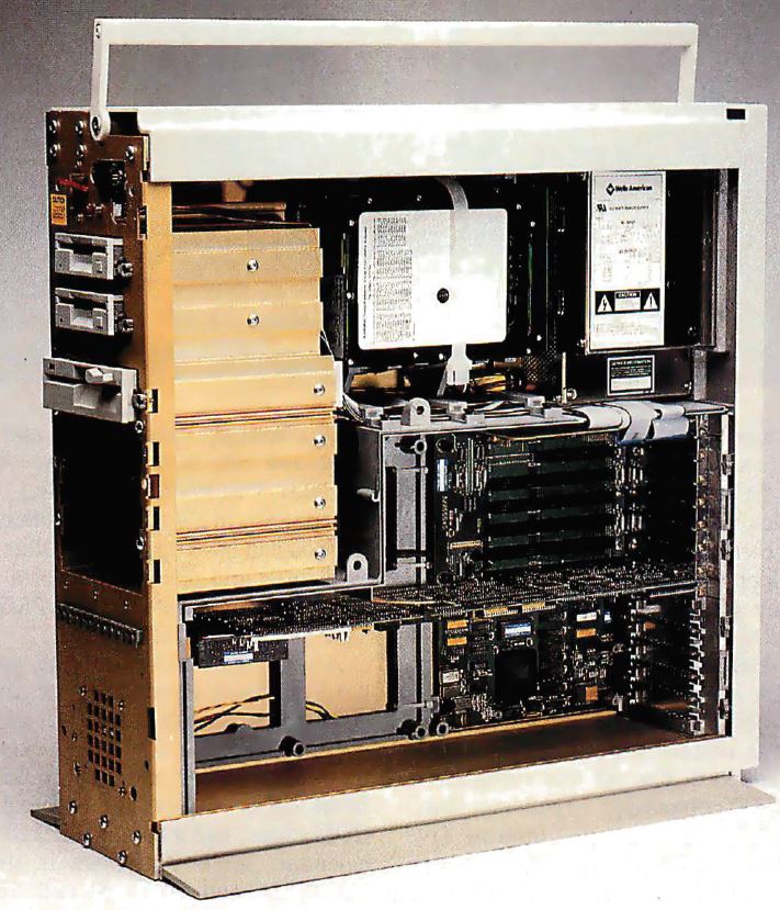
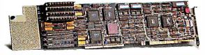
Finally we can see where the CPU board is, in the center. A snippet mentioned that the CPU board was fastened securely on one end. My guess was that it used a ISA style slot bracket on the rear end, and the front end slid into a tab bracket like on a 95.
See the hard drive cables coming off the top AT card? That might be an Adaptec ACB-2320 10-megabit-per-second ESDI controller in the top AT slots.
"fans-one at the bottom front of the unit that blows out enough air that you can feel it if you wear shorts, and one at the top rear inside the power display case." [ed. PSU?]
Just a SWAG, but the "L" shaped board to the right of the speaker and to the left of the Bus Modules -MIGHT- be the "PS/2 adapter module". Note the AT bus only system lacks ANY board to the left of the Bus Module socket area...
Notice the black connector sockets on the right edge of the PS/2 module? The MCA Bus Module has a matching socket on it's left side. Notice the single AT Bus Module -LACKS- a socket on it's left side. But it doesn't need one, since the CPU Board plugs into the I/O Module via the ISA riser.
I would guess that the MCA slots communicate to I/O Module ports through the MCA contacts on the CPU card over to the AT contacts, then down through the ISA riser.
Looking at this horrid quality image I would guess the AT contacts are on the right, MCA contacts on the left. If you glance up at the multi-bus system, you will see the possible "PS/2 adapter module".
80286 CPU board is based on C&T NEAT chipset. Harris 80C286 CPU.
Switch selectable 115v/230v 220-watt power supply
I/O module
 DB25 RS-232C serial port
DB9 RS-232C serial port
DB25 parallel port
PS/2-style 6-pin DIN keyboard connector
PS/2-style 6-pin DIN mouse connector
Rectangular opening between lower PS/2 connector and DB9 Video might be a board-mounted flip switch block to configure the DB9 video port...
DB-9 digital connector
DB-15 VGA analog. VGA , EGA, CGA, MDA, and Hercules graphics.
Paradise PVGA1A chip
This board can handle up to four floppy disk drives.
| AT Bus Module |
MCA Bus Module |
 |
 |
"The AT bus module has seven AT -compatible expansion slots, while the PS/2 module contains five Micro Channel-compatible slots and one AT-compatible slot."
"You can pick an AT- or PS/2 Micro Channel compatible bus module; if you choose the PS/2 bus module, you also need a special PS/2 adapter. The AT bus module has seven AT -compatible expansion slots, while the PS/2 module contains five Micro Channel-compatible slots and one AT-compatible slot."
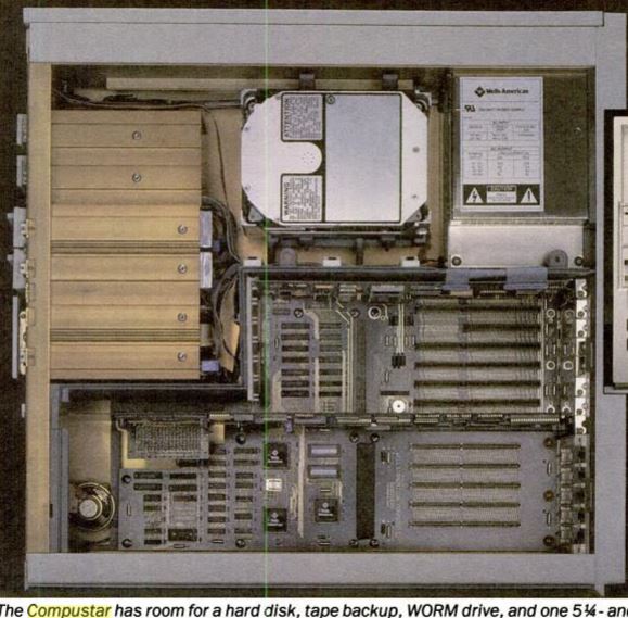
If you look at the top image of an open case, there is a planar UNDER the top AT Bus module. As there was no second Bus Module, you can see the planar's lower half. Note that it does not extend past the black frame in the middle of the case.
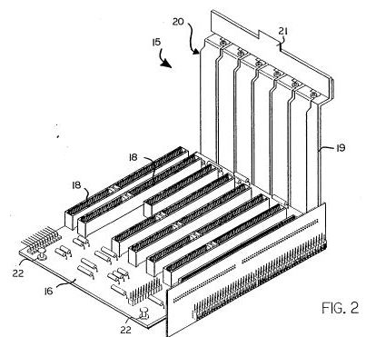
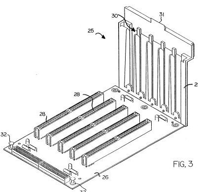
Looking at the case images, you can see the push-pin fittings, like in the 8570. Look at the patent drawings, and you will see the snap fittings on the left end of the Bus Modules.
There must be some special mojo AT slot on the I/O module (I prefer to call it a planar), and the "ISA" slot mentioned in articles -MIGHT- be the riser which connects the AT bus looking edge contacts on the CPU card to the special mojo slot on the I/O planar.
I was thinking in two dimensions while the CompuStar used that black frame as a standoff in order to mount another set of PCBs above the I/O planar....
"So, in a single CompuStar chassis, you can have up to 13 AT slots, or 10 PS/2 slots and one AT slot, or a mixed bag of seven AT slots and five PS/2 slots." AT Bus Module has 6x 16-bit, 1x 8 bit, but the internal structure gets in way of one slot so the limit is 13 slots. But there are only 11 externally accessible slots...
Interleaved memory banks, one bank of memory recharges while the other is ready to go.... nice improvement on traditional two bank interleaving: If you have four identical memory modules, it can do four way interleaving, so that three banks are ready while one is recharging. On its 80386-based CPU modules, interleaving is in addition to an Intel 82385 cache controller and 32K bytes of 35-ns SRAM cache.
"CPU module, which contains a CPU, a socket for a math coprocessor, memory sockets, the ROM BIOS, sockets for two expansion ROM chips, and a battery-backed clock/
calendar."
The 8086 CPU board runs at 5 and 10 MHz and can hold up to 2.5 megabytes of RAM — and EMS 4.0 support is built onto the board. The 8086 CPU board DOES NOT support the PS/2 Adapter module....
The 80286 CPU board runs at 20 MHz (with compatibility speeds of 6, 8, 10, 12, and 16 MHz) and holds up to 16 megabytes of RAM (the second 8 megabytes require an extender kit). Memory over 1 megabyte can be configured for any mixture of extended (protected-mode) and expanded (EMS) memory.
386 boards: 16 MHz, 20 MHz, and 25 MHz (each also runs at 10 MHz for compatibility). All 386 boards can hold up to 16 megabytes of RAM.
There will be a 386SX board as well, for users who need 32-bit computation without the expense of 32-bit memory.
All the CPU boards accept the standard Intel math coprocessors; the 386 boards can also take the Weitek math coprocessors. The 286 and 386 boards use 80-nanosecond dynamic RAM; the 8086 uses 120-nanosecond DRAM.
The 80286 can run at 16, 12, 10, 8, or 6 MHz. Three different oscillators (20, 16, 12 MHz) are divided by a flip-flop divider in order to provide 10, 8, and 6 MHz speeds. Control the speed with Ctrl/ Alt/ + combination to raise the speed, or Ctrl/ Alt/ - to lower it. The system beeps once each time you lower its speed, and twice each time you raise the speed. A DOS utility, SPEED.EXE, can set the speed from the DOS command line."
Setup Disk
Includes Wells's setup program (also in ROM and accessible via the Ctrl/Esc key combination); a LIM/EMS driver; system video mode utility; port assignments and memory usage control (includes its use of interleaving and shadow RAM); special disk drivers (including Extended Diskette Drive BIOS); and the LED and compatibility speed control programs.
Options
CompuStar Base Model 100 (huh: 90, 95, 100...)
AT-compatible primary bus module
AT-compatible secondary bus module
PS/2-compatible primary bus module
PS/2-compatible secondary bus module
PS/2 adapter module
8086 CPU module (does NOT support MCA Bus Modules)
80286 CPU module
80286 memory-extender kit
16-MHz 80386 CPU module
20-MHz 80386 CPU module
Size:
24 x 7.5 x 26 inches; 66 lbs (weight from 50 to 90 lbs, depending on configuration)
Processor: 20-MHz 16-bit Intel 80286; 10- MHz Intel 80287 coprocessor
Memory: 1MB 16-bit 80-ns DRAM on 80286 CPU module, expandable to 16MB; 128KB of BIOS ROM