|
@6FC1.ADF WD StarCard PLUS/A (WD8003ST/A) @6FC2.ADF WD EtherCard PLUS 10T/A (WD8003W/A) RJ45 / AUI  SuperDisk version
1.7 (*.IMA format) from Jose Deras SuperDisk version
1.7 (*.IMA format) from Jose Deras EtherCard PLUS 10T/A User Installation Manual from Jose Deras Comparison of the Performance of Various MCA Ethernet Adapters I DIMMly remember that theWD8003 adapters are supported under AIX for PS/2. SMC acquired Western Digital's NICs. So a WD8003
corresponds to a Elite 16 8003. 8013-UGD.pdf 8013(/A) User's Guide (Had it somewhere...) adf200.exe (8.0K) Elite ADF Configuration file for our MCA adapters asd700.exe (1007.5K) Latest SuperDisk for Elite/Ultra adapters dia401.exe (83.4K) Diagnose utility for Elite and Ultra Adapters gez122.exe (41.8K) New EZSETUP For Elite EtherCard Plus/ Ultra in Dos Ver1.08 gpk115.exe (70.8K) Packet Drvr V11.5 for use with 8/16 Bit Elite/Ultra Adapter. setjmp.exe (7.8K) Switch setting for most of the Elite Ethernet Line of Cards. ETHER.EXE 8013 Drivers and utils DOS/WfW/W95/NT4/OS2/Packet gsm101.exe SMC SCO AHS 5.1 NETWORK DRIVERS gsu124.exe SMC SCO LLI 3.4 DRIVER guw402.exe SMC UNIXWARE 2.x Driver smc-ultra.c SMC Ultra Ethernet driver for Linux
WD EtherCard PLUS 10T/A (WD8003W/A) 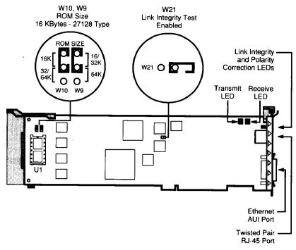 WD EtherCard PLUS/A (WD8003E/A or WD8003ET/A) BNC / AUI 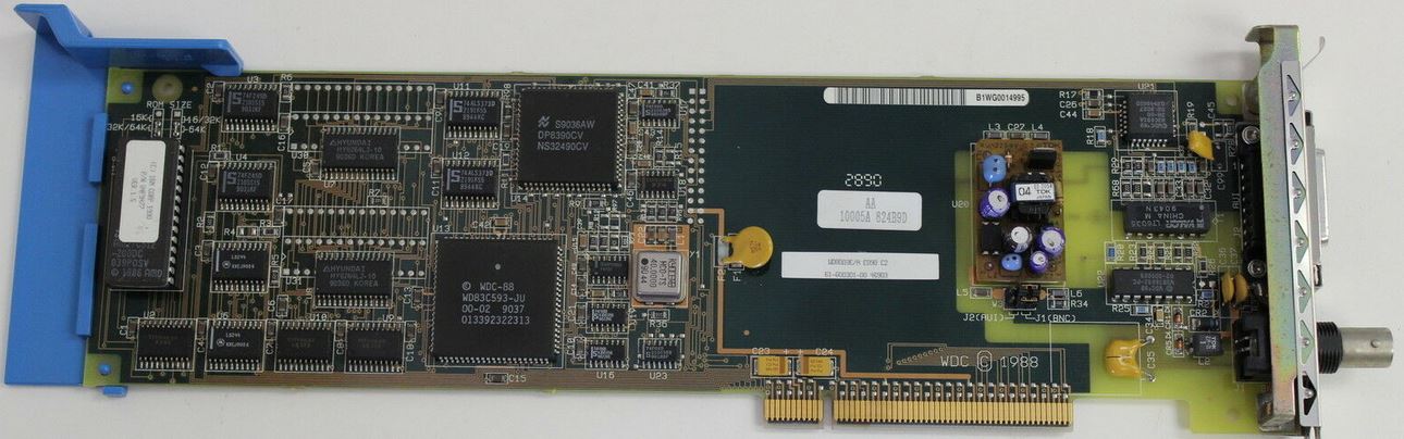 WD8003E snippets J2 / J1 selects AUI or BNC on the WD8003E/A U8, 9 HY6264LJ-10 U13 WDC83C593-JU U14 DP8390CV WD EtherCard PLUS 10T/A (WD8003W/A) RJ45 / AUI 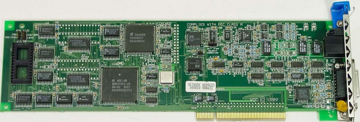 U8, 9 HY6264LJ-10 U13 WDC83C593-JU U14 DP8390CV U20 DI 60001-000 U21 DI 60001-000 U39 WD 83C691A LED Indicators P - Polarity Correction LED (Green) On when twisted-pair received signal polarity is correct and link is valid ("L" indicator is on). If this is off when "L" is on, the adapter will still operate properly, but the received signal polarity is reversed. L - Link Integrity LED (Green) On when twisted-pair link is valid (10BaseT Link Test Pass mode) or when W21 (Link Integrity Test) is installed. It shows that RJ-45 is being used instead of AUI. T - Transmit LED (Yellow) This flashes when the adapter is transmitting. R - Receive LED (Green) This flashes when adapter is receiving. It also flashes when transmit data from adapter is looped back to receiver by on-board twisted-pair transceiver or by an external transceiver connected to AUI. ROM Size Jumpers (W9, W10) 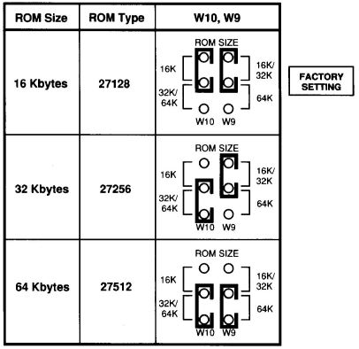 AMD27C128-200, 27C256, 27C512-200 will work as well. W21 - Link Integrity Test 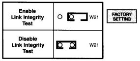
With this jumper (see Figure 1) removed, which is the normal setting, link integrity test pulses are transmitted and received according to the 10BaseT standard. If this jumper is installed, the link integrity test is NOT performed (no link test pulses are generated, and received link test pulses are ignored). The twisted-pair port (RJ-45) is enabled and the AUi port is disabled. The adapter board will operate correctly when used in "StarLAN IO" networks without Link Integrity such as those by AT&T and Hewlett Packard, even though "StarLAN 1 O" without Link Integrity is not fully 10BaseT compatible. To operate the LAN adapter in this mode, the link integrity test function must be disabled (Jumper installed). W20 Polarity Connection If you have an Ethernet 10BaseT adapter that has an additional jumper labelled W20 "Polarity Correction'" please leave this jumper in the factory installed on position (as labeled on the board). ADF Sections @6FC0.ADF WD EtherCard PLUS/A (WD8003E/A or WD8003ET/A) @6FC1.ADF WD StarCard PLUS/A (WD8003ST/A) @6FC2.ADF WD EtherCard PLUS 10T/A (WD8003W/A All three adapter's ADF sections are identical <EXCEPT> the Fixed Resources. Adapter IO Space IO address space used by adapter. Default is < IO Base 280h > <" IO Base 280 " io 0280-029F>, 200 (0200-021F), 220 (0220-023F), 240 (0240-025F), 260 (0260-027F), 2A0 (02A0-02BF), 2C0 (02C0-02DF), 2E0 (02E0-02FF), 300 (0300-031F), 320 (0320-033F), 340 (0340-035F), 360 (0360-037F), 380 (0380-039F), 3A0 (03A0h-03BF), 3C0 (03C0-03DF), 3E0 (03E0-03FF) Shared Ram Space (16K Bytes) Shared RAM memory address space. Default is < Ram Base D0000h >." <" Ram Base D0000h " 0D0000-0D3FFF>, C0000 (C0000-C3FFF), C4000 (C4000-C7FFF), C8000 (C8000-CBFFF), CC000 (CC000-CFFFF), D4000 (D4000h-D7FFF), D8000 (D8000h-DBFFF), DC000 (DC000-DFFFF) BIOS ROM Space The BIOS ROM can be disabled or enabled. When enabled, different sizes and address spaces can be assigned. Default is <BIOS ROM Disabled> <" BIOS ROM Disabled ">, 16K C0000 (C0000-0C3FFF), C4000 (C4000-0C7FFF), C8000 (C8000-0CBFFF), CC000 (CC000-0CFFFF), D0000 (D0000-0D3FFF), D4000 (D4000-0D7FFF), D8000 (D8000-0DBFFF), DC000 (DC000-0DFFFF) 32K C0000 (C0000-C7FFF), C8000 (C8000-CFFFF), D0000 (D0000-D7FFF), D8000 (D8000-DFFFF) 64K C0000 (C0000-CFFFF), D0000 (D0000-0DFFFF) Interrupt Level Interrupt level adapter uses. Default is <Level 3> <"Level 3">, 4, 10, 15 |