|
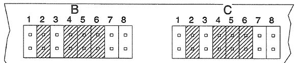
POSN |
Group
B Description |
|
POSN |
Group
C Description |
|
1 |
Pull
up xmit line |
|
1 |
Pull
up xmit line |
|
2 |
Terminate
xmit line |
|
2 |
Terminate
xmit line |
|
3 |
Pull
down xmit line |
|
3 |
Pull
down xmit line |
|
4 |
Terminate
rcv line |
|
4 |
Terminate
rcv line |
|
5 |
Pull
down rcv line |
|
5 |
Pull
down rcv line |
|
6 |
Pull
up rcv line |
|
6 |
Pull
up rcv line |
|
7 |
RTS
control RS-422/485 |
|
7 |
CTS
control RS-422/485 |
|
8 |
Not
used |
|
8 |
Not
used |
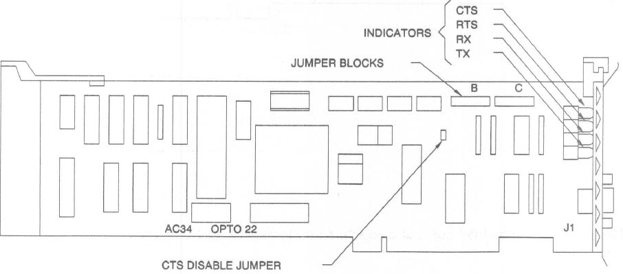
Communicating With OPTOMUX
Before applying power to OPTOMUX Brain Board(s), set the baud rate and command protocol on the OPTOMUX Brain Board(s). The baud rate and command protocol are selected by the B group of jumpers on the OPTOMUX Brain Board(s). (Please refer to the OPTOMUX B1 and B2 Digital and Analog Brain Boards Operations Manual, Form 203 for additional information.)
For the checkout, remove all of the group B jumpers from one OPTOMUX Brain Board and disconnect all other OPTOMUX Brain Boards on the network. This will select a baud rate of 300, the four-pass protocol, and an OPTOMUX address of 255.
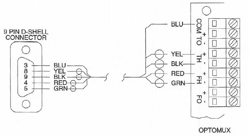
Connect the D shell connector to the AC34 card and turn on the power to the IBM PS/2 and the OPTOMUX. To test the link, enter the IBM BASIC interpreter and type in the following program. The underlined part of line ten must be changed to COM1 when using the AC34 card as communications port one.
10 OPEN "COM2:300,N,8,1,RS,CS,CD,DS" AS #1
20 PRINT #1,°>FFACD"
30 INPUT #1,B$
40 PRINT B$
When running the program, both the receive and transmit LED's on the OPTOMUX will flash. The IBM PS/2 will display the AFFACD on the screen. If nothing is displayed, verify that all the wiring has been done correctly.