After connecting the
LC2 to the Host, configure and initialize the host's serial port
with the following parameters:
BAUD RATE:....
300, 1200, 2400 4800, 9600, 19200 or
38400
START BITS:
1
STOP BITS:.
1
DATA BITS:.
8
PARITY:. .
NONE
If you are using an IBM Personal Computer or
compatible as a host, the utility LCTERM simulates a terminal with
upload and download capabilities. The documentation (what little
there is) is in LCTERM.TXT.
After the host is configured, apply power to
LC2. If everything is working correctly, a sign on message should
appear at the host. If this message does not appear, make sure the
"AUTO" jumper is NOT installed. If it is installed, turn power off
on LC2, remove the jumper, and turn power back on. If you still do
not get any response, check the LED indicator "TH" to be sure it
flashes briefly when power is applied. This LED indicates that LC4
is transmitting to the host (try a slower baud rate to make it
easier to view the flashing LED). Double check the wiring, LC2
configuration, and host configuration to make sure there are no
errors.
LCterm Terminal emulation program used with
LC2. Files can be down-loaded and up-loaded between LC2 and the IBM
PC. LCterm Help File Word *.DOC
format. LC2 Newer
version, 1992. 005019B
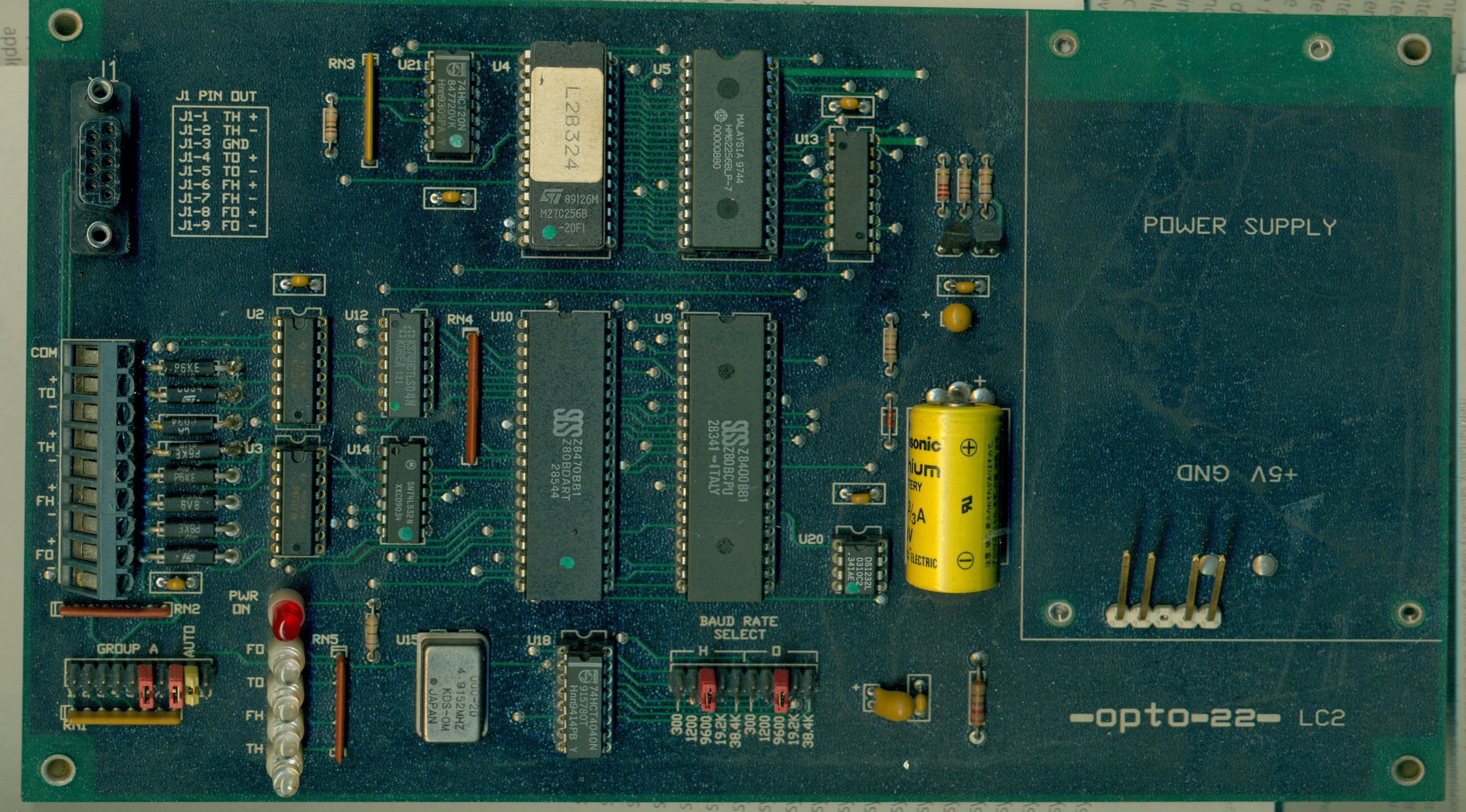
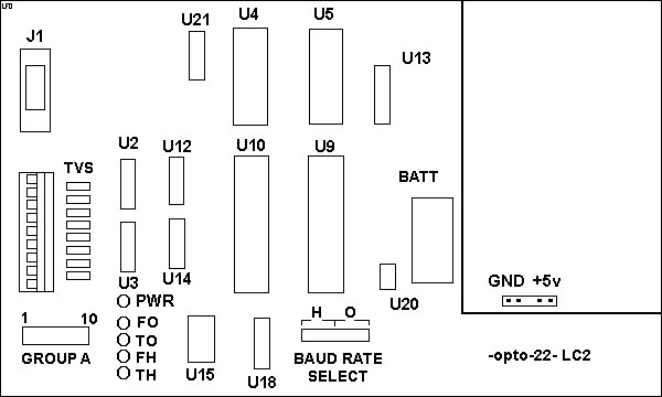
AUTO - Boot Jumper 9 Battery - BR-2/3A, 3v BAUD RATE SELECT, H and
O GROUP A - Term and Bias J1 - RS-422/485 DB9 Optomux LEDs - FO, TO,
FH, TH PWR ON - Power LED TVS - P6KE 6V8 CA (8x) U2,3 TI 75174N U4 - M27C256B-20F1
My apologies, the USB scanner software is bundled, and too much
light bleed, washes out image...
AUTO jumper runs to Z80B DART Pin 10, Wait/ReadyA, W/RDYA (inverse)
Datasheets: DS1232 MicroMonitor Datasheet
(Power supply, software execution, and external override)
DS1232L Pin 1 Pushbutton Reset Input, PBRST (inverse)
connects to Z80B CPU Pin 25, RESET (inverse)
DS1232L Pin 7 Strobe Input, ST (inverse) connects to
Z80B DART Pin 16 DTRA (inverse) HM62256B 256k SRAM (32-kword
8-bit) Datasheet RTC-72421 4-bit Real Time
Clock Module Datasheet Transil P6KE 6V8 CA Transient
Voltage Surge Suppressor (Bi-Directional) Datasheet NOTE:
Bi-directional devices are not marked with a Cathode band! Z80BCPU (Z8400BB1) CPU
Datasheet Z80BDART (Z8470BB1) Dual
Asynchronous Receiver/Transmitter Datasheet SN75174N Quadruple Differential
Line Driver Datasheet M27C256B 256 Kbit (32Kb x 8) UV
EPROM Datasheet 74HCT4040N 12-stage Binary
Ripple Counter Datasheet 74HCT20N Dual 4-Input NAND Gate
Datasheet 74LS32N Quadruple 2-Input
Positive-OR Gates Datasheet
BAUD RATE SELECT Jumpers
Set the Baud rate for communicating with Host (H) and Optomux (O)
network.
Host can be a PC or another Optomux device upstream.
Optomux is for downstream connection with an Optomux device.
300 (Modem or Radio Link)
1200 (Modem or Radio Link)
9600 (Default)
19.2K
38.4K
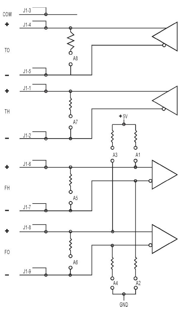
Group A Jumpers
Provides termination and bias resistor connections for the
RS-422/485 port. NOTE: I do not have an LC2
hardware guide. This is a guess, but the traces do run from J1 to
the screw terminals to the Group A Jumpers. Maximum RS-422/485 Serial Speeds for Both
Optomux (O) and Host (H)
Old, 4 CMOS RAM chips - 19.2Kb circa 1987
New, 1 CMOS RAM chip, - 38.4Kb circa 1992
Old - 4x HM6264A Series
8192-word × 8-bit High Speed CMOS SRAM 32K total
New - 1x HY62256ALP-100
32k x 8-Bit CMOS SRAM
Old - Watchdog crystal - 32kHz feeds U13 - looks like an NS
watchdog IC.
New DB9 RS-422 Port 0466
AC7 RS232 to RS422 Converter (AC7 is 12v DC) 0233 AC7A -
AC7B Users Guide RS232-RS422/485 Converter (AC7A is 120v, AC7B is
220v) 0960
AC7A/B Adapter Card Data Sheet RS232-RS422/485 Converter (AC7A
is 120v, AC7B is 220v)