|
Internal/External I/O Controller (Type 4-4) 8D77 (4-4) SCSI SE High Performance Internal/External I/O Controller FC 2410, 2831 WD33C93B
WD33C93B Datasheet
(52G5484, 52G5483,
52G7504, 52G7509, 11H4779, 11H4780, 52G1171, 2410,
2830) SCSI-2 SE I/O Controller (Type 4-4): OK, what do we got? Accepts multiple commands per device at a time from system SCSI-2 data rate of up to 10MB per second (synchronous protocol) SCSI initiator SCSI target SCSI parity Bus Master Streaming Data Support [I think it MUST support Bus Fairness as well] Address and Data Parity Support Supports Command Tagged Queuing (as SCSI initiator) Interrupt levels 3, 4, 5, 7, 10, 11, 12, 14 HPDB50 external SCSI Port [Oh YES! YES!]
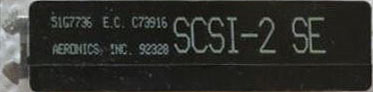
SCSI I/O Controller 4-4, FRU 52G5483 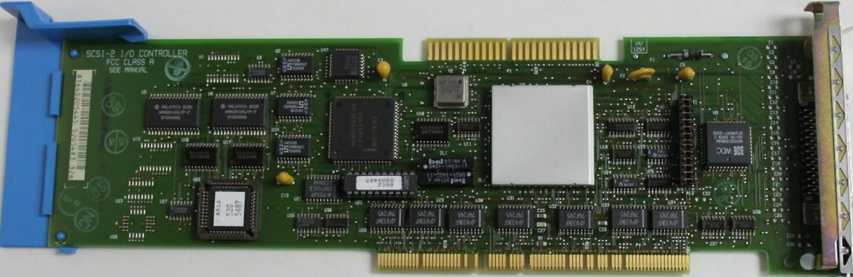
All versions of the 4-4 use 32G0215ESD [Entry Systems
Division]. There seems to be a connection between the
later production dates and the "00-04" revision of the
WD33C93B. 32G0215 Laser Etched - 93-ish mfr, "00-02" WD33C93B 32G0215ESD MCA Bus interface ??? DL1,2 bel
0401-1403-11 High-Speed 4 Pin SIP Passive Delay
Module bel App 1-R1
Pulse Shaping / Clock Pulse Generation Circuits Y2 is a 39.9500 MHz osc, that provides an input clock
to the WD33C93B I also suspect that 39.9500 MHz osc is used to provide
the clock [suitably divided] for other components. Three possible firmware chips, the socketed PLCC44
[U26], the socketed DIP-20 [U22], and the surface
mounted PLCC [U47]above the 80C186XL20. I see two digital signal regenerators [DL1,2] between the DIP-20 and the 32G0215. J1 (also called P3) High
Availability Jumper P3 High Avail Jumper 2 pieces 42F7525, 42F7526 So, can we make a kludge of an internal terminator
using the J1headers? DIP or SIP resistor network? SCSI
TERMINATORS (Purpose and Usage)
Terminators: The FPT-3 is generally
used on the the internal end of the cable, and the
FPT-18 is used on the external end of the cable.
SCSI Termination From HERE
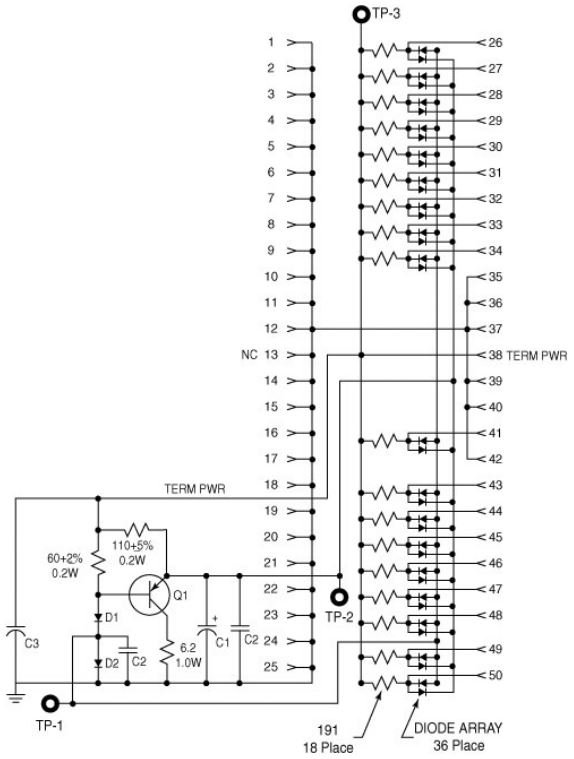
FPT is an even better form of active termination, in which diode clamps are added to eliminate signal overshoot and undershoot. The trick is that instead of clamping to +5 and ground, these terminators clamp to the output of two regulated voltages. This arrangement enables the clamping diodes to eliminate signal overshoot and undershoot, especially at higher signaling speeds and over longer distances. FPT is technically not found in the SCSI specifications but is a superior type of termination for SE applications that experience high levels of electrical noise. FPT terminators are available in several versions.
FPT-3 and FPT-18 versions are available for 8-bit
standard SCSI (Figure 7.18 shows the schematic for an
FTP-18 terminator), whereas the FPT-27 is available for
16-bit (Wide) SCSI. The FPT-3 version forces the three
most highly active SCSI signals on the 8-bit SCSI bus to
be perfect, whereas the FPT-18 forces all the SCSI
signals on the 8-bit bus except grounds to be perfect.
FPT-27 also forces all the 16-bit Wide SCSI signals
except grounds to be perfect. FPT-18 SCSI terminator
schematic
Card edge, FPT-3 00G0972 "50-position
card edge terminator"
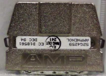
50-Position External Terminator FPT-18C 52G4259 50-pin, high-density, external,
FPT-18+ 51G7737
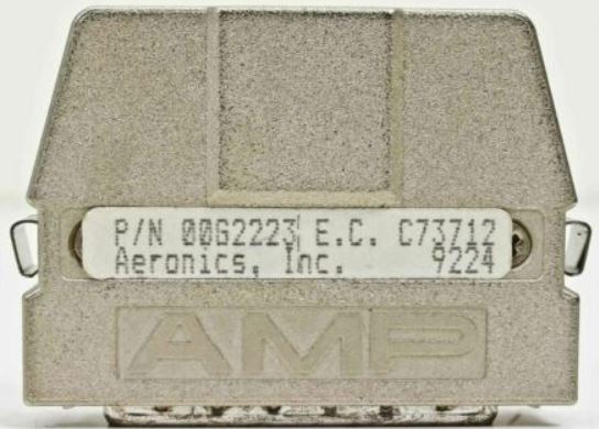
Aeronics
00G2223 FPT-3
52G4259
FPT-18C
52G4259
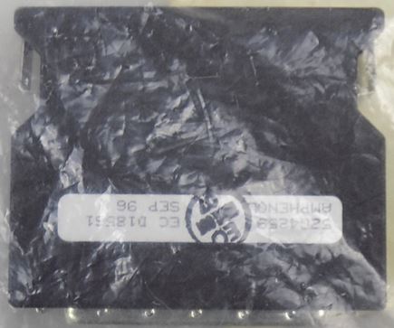
Black FPT-18C (different
case)
Same P/N (52G4259) and EC (D18561).
My SWAG is that IBM moved from the AMP metal shell to
the black one due to cost. I can't verify the
electronics being the same, but they probably are...
External Terminator for C50 Connector
on External SCSI Cable
222-12-50-035 CINCH
Stephan Goll says: To make a summary: AIX has a database called ODM. In this database there are the definitions and suggestions for configuring all the cards not configured before IPL. Cards where AIX can boot from, well, should be configured somehow, I believe by the ROS (or BIOS). Makes sense, because only the ROS knows from where the box can IPL. And remember, AIX uses a two stage boot process, first it boots in minimal mode, configures the cards using the ODM, and then it boots again with the system fully configured (so it is written in my AIX survival guide). Overload Protection and Terminator Power (Term Power) The SCSI controller provides term power for the SCSI bus; connect devices to the bus so they do not provide term power. The controller uses a fuse that must be replaced after failure. Do not connect or disconnect any SCSI device while power is on. Such “hot plugging” is forbidden because this practice may blow the controller fuse, corrupt data or permanently damage SCSI controller chips in controllers or devices. The fuse on an SCSI controller protects the external and internal SCSI bus. The fuse may be blown by a defective cable, terminator, or device attached to the controller, but not by a defective controller. |