|
Cisco 3640 Multiservice
Platform
Still assembling my 3640. and awaiting some books. If you
want to contact
ME, it won't do you much good.Cisco 3600 Series Routers Hardware Installation Guide Installing Power Supplies in Cisco 3600 Series Routers Installing the Grounding Lug on Cisco 2600 and Cisco 3600 Series Routers Rack or Wall-Mounting Cisco 3600 Series Routers and the Redundant Power System Upgrading System Memory in Cisco 3600 Series Routers Cisco 2600 and 3600 Hints and Tricks Cisco 3620 and Cisco 3640 Router Quick Start Guide Center-Mount Bracket Installation Guide for Cisco 3640 Series Routers Password Recovery Procedure for the Cisco 3600 and 3800 Series Routers Auxiliary Port, Console Port, And Adapter Pinouts For Cisco 1000, 1600, 2500, 2600, And 3600 Series Routers Cisco 3600 Series Router Architecture Cisco RPS Hardware Installation Guide 
J3 BAUD RST - Jumper J3 on the motherboard of the Cisco 2600 and 3600 Series Routers controls the speed reset. The factory default position of the shunt shorts pins 2-3. When the shunt is moved to pins 1-2, the console is reset to 9600 baud on the next power cycle. The following figures show the location of the console reset jumper, labeled DUART_RST or BAUD_RST. Memory 72 pin SIMMs, 60nS speed, Tin leads. Both non-parity and parity SIMMs supported. Just to be simple, all one type or the other... • Cisco 3640: Supports either 32- or 64-bit operation. Router performance is approximately 20 percent slower in 32-bit mode than in 64-bit mode. To use 64-bit mode, you must install DRAM SIMMs in pairs of the same size. Generally, basic software feature sets (such as IP) use 32-bit DRAM SIMMs and robust software feature sets (such as Enterprise) use 64-bit DRAM SIMMs. NOTE: I dimly remember a snippet that the 3640 will support parity if both SIMMs in a bank are parity. If not, the bank will be treated as non-parity {Ed}. Follow these rules to use 64-bit operation: • SIMMs in banks 0 and 1 must: – Same size (in megabytes) – Have the same access time (in nanoseconds). • SIMMs in banks 2 and 3 must: – Same size (in megabytes), and the same size or smaller than those in banks 0 and 1 – Have the same access time (in nanoseconds) 3640 Front View 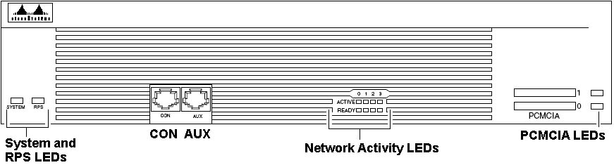 The main difference between the console and auxiliary ports is that the auxiliary port supports hardware flow control and the console port does not. Because the auxiliary port supports flow control, it is ideally suited for use with the high-speed transmissions of a modem. Console terminals transmit at slower speeds than modems; therefore, the console port is ideally suited for use with console terminals. System LED
RPS LED
|