| • |
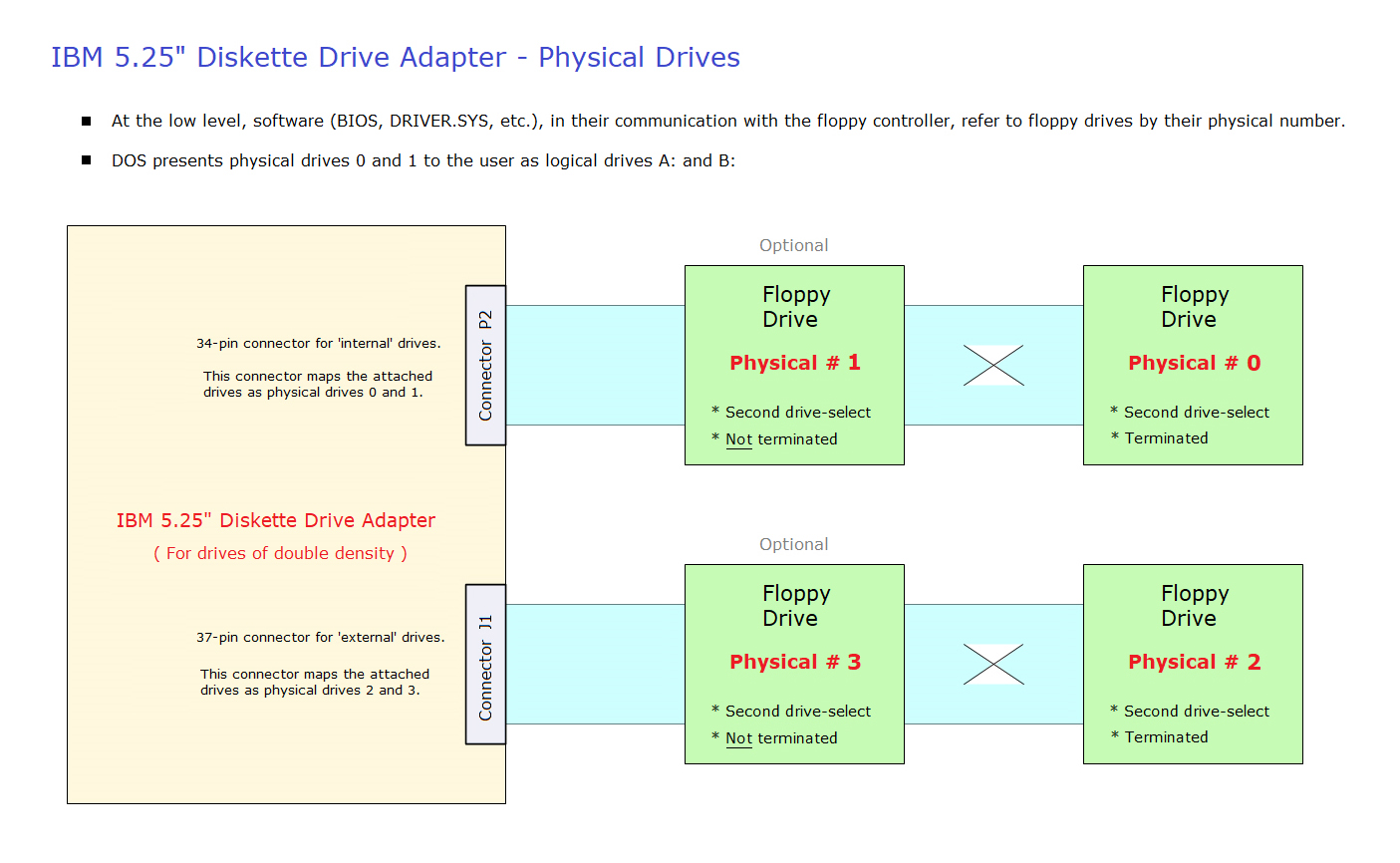
Cabling and termination is as per connector P2. |
| • |
Connector J1 does not supply power to the drive. |
| • |
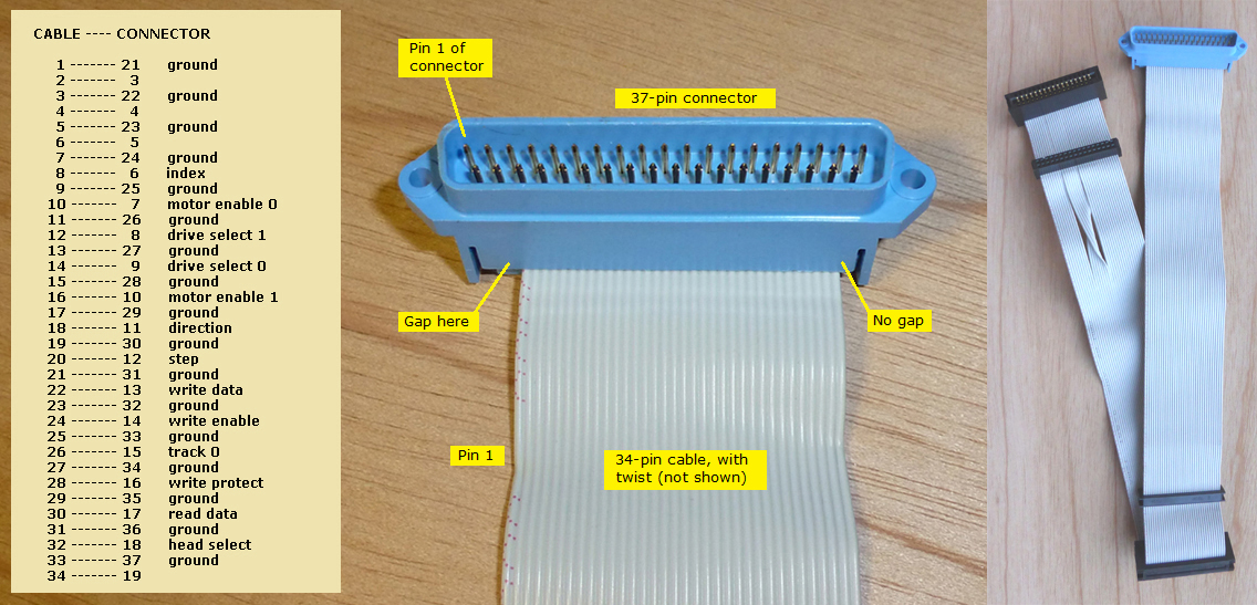
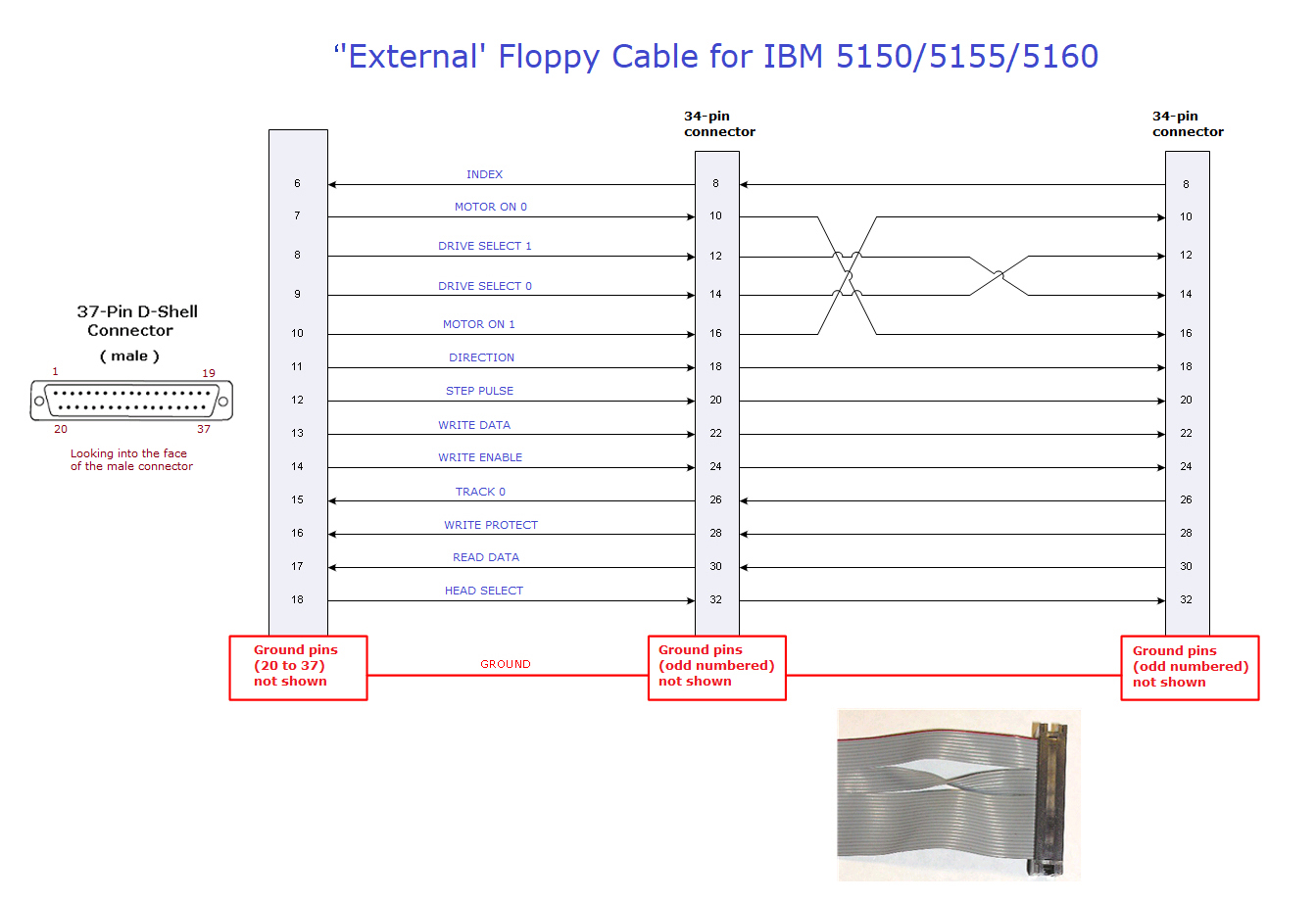
If connecting an external 360K drive, then set the floppy drive count switches on the IBM 5150/5155/5160 motherboard as appropriate - see here. Details of a suitable control/data cable are at here and here. Do not forget to power the drive. |
| • |
If you are using DOS 4 or earlier, DOS will present the first external 360K floppy drive (physical #2) as C:, and if present, the second external 360K floppy drive (physical #3) as D:
In later versions of DOS, drive letters for external floppy drives will follow the letters of hard drives.
|
| • |
Click here for detailed information on how to use an external 3.5" diskette drive in order to access 720K diskettes. |
| • |
Reminder: 1.2M floppy drives are not going to work on the IBM 5.25" Diskette Drive Adapter. |