| On-screen output |
Checkpoints to LPT ports |
Checkpoints to COM1 |
Speaker beep |
Comment | |
|---|---|---|---|---|---|
| Option #1: MDA video card | Yes | Yes | Yes | Yes | |
| Option #2: CGA video card | Yes | Yes | Yes | Yes | |
| Option #3: 4KB RAM at address A0000 | No | Yes | Yes | Yes | |
| Option #4: 4KB RAM at address B0000 | No | Yes | Yes | Yes | The diagnostic will think that you have an MDA video card. |
| Option #5: 4KB RAM at address B8000 | No | Yes | Yes | Yes | The diagnostic will think that you have a CGA video card. |
| Option #6: None of the above | No | Limited | Limited | Yes |
| 1. | The 'Hot NMI' test is known to fail if either: - Math coprocessor (8087 chip) is absent and you have switch 2 in switch block SW1 in the wrong position for that (off). - Math coprocessor (8087 chip) is present and is faulty in a particular way. |
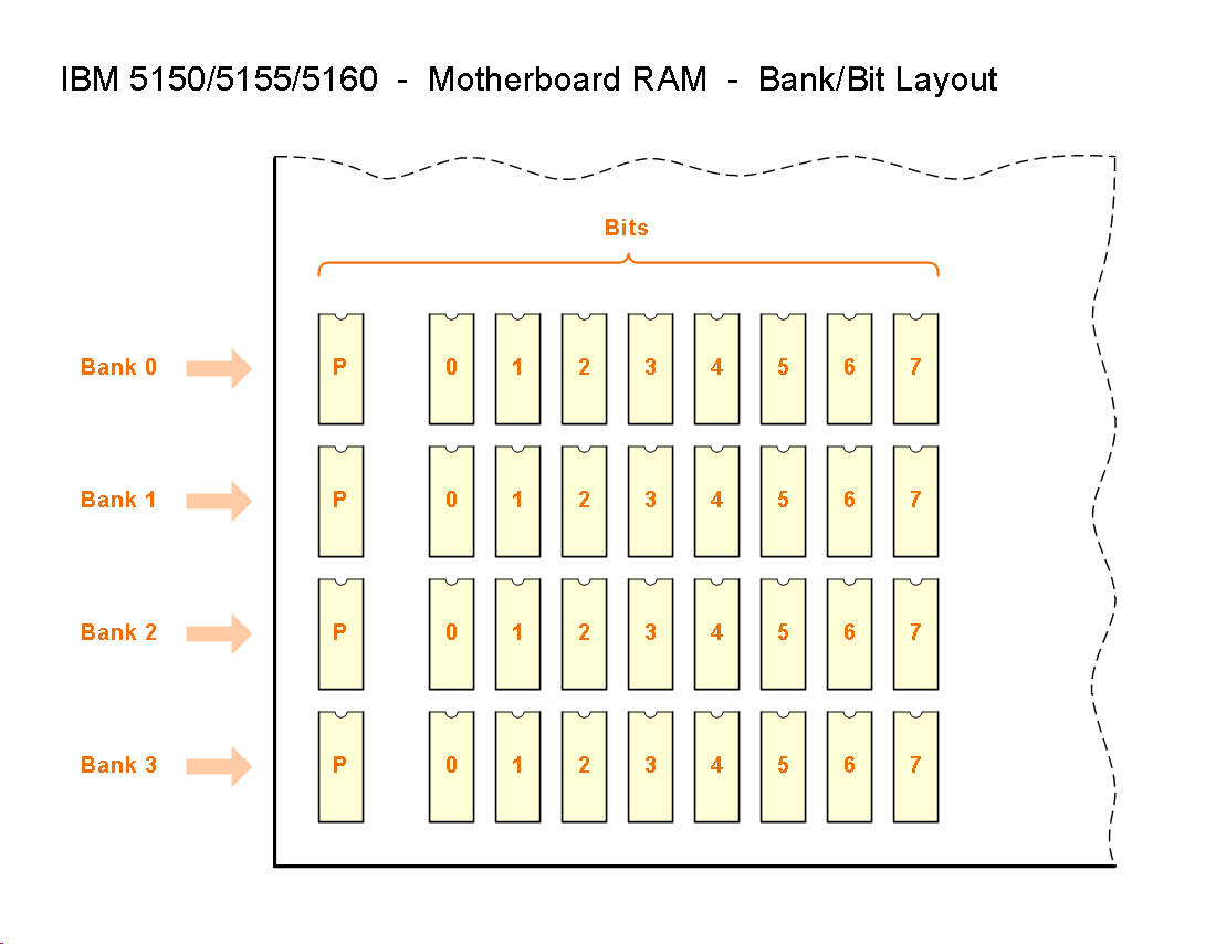
| 2. | If there is a faulty RAM chip for parity, it will not be shown until all faulty RAM chip/s for data (in the same bank) have been rectified. |
| 3. | All or some of the 'Check ROM at Fx000' tests may fail because there are no ROM's at the tested addresses. |
| 1. | Both an MDA and CGA card fitted, with monitor connected to the CGA card. In this scenario, the only thing that you will see on the CGA monitor is, "Ruud's Diagnostic ROM for PC/XT" - everything else goes to the MDA card+monitor. This is not a bug. This diagnostic expects only one video card fitted, of MDA or CGA. |
| Condition | Observed behaviour | Comment |
|---|---|---|
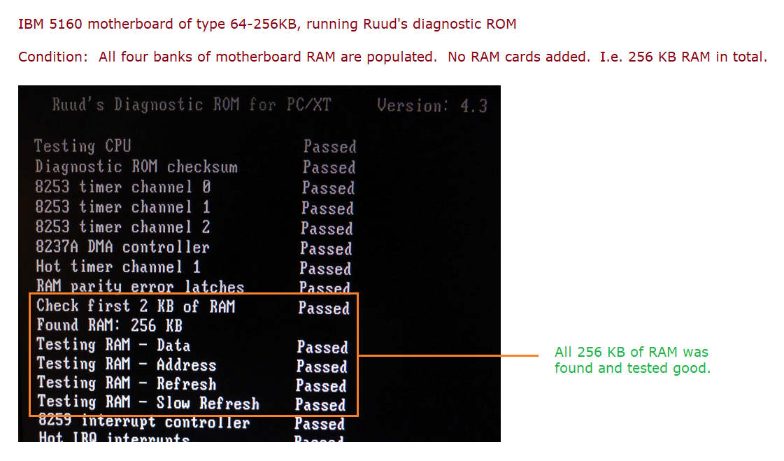
| All 4 banks are good | See the partial screen shot at here. | 4 banks of 64 KB = 256 KB |
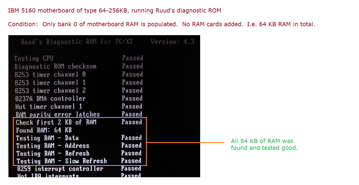
| Only bank 0 is populated, and all chips in it are good | See the partial screen shot at here. | 1 bank of 64 KB = 64 KB |
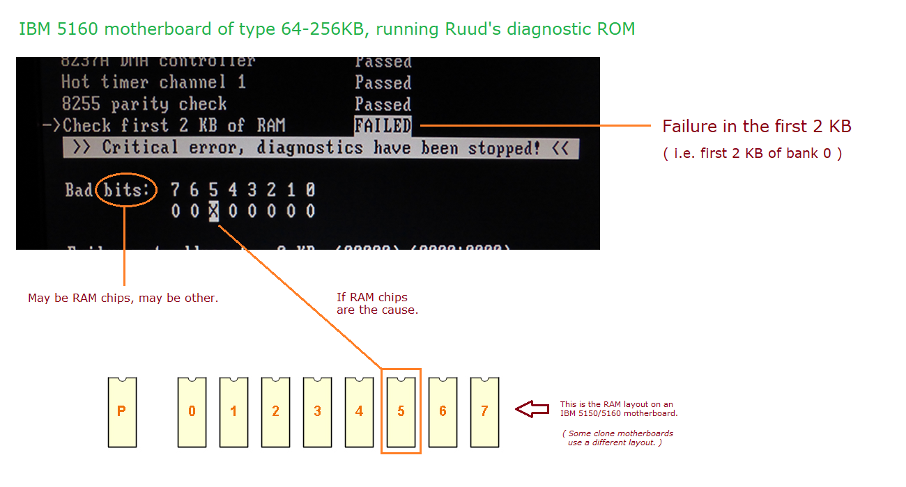
| A single chip has failed, in bank 0. Failure affects the first 2K of addresses. |
See the partial screen shot at here. | • Includes a complete failure of chip (i.e. affecting all addresses in chip). See note 1 below. |
A single chip has failed, in bank 0. Failure is after the first 2K of addresses. |
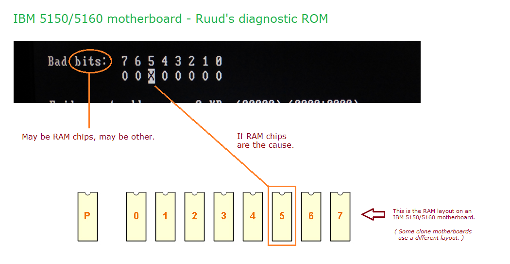
The 'Testing RAM - Data' test fails. Under that is: • "Failure at address: xx KB" is displayed, where 'xx' is a figure between 2 KB and 63 KB. • The bad bit is displayed (example at here). |
• 64-256KB motherboard. |
A single chip has failed, in bank 1 |
The 'Testing RAM - Data' test fails. Under that is: • "Failure at address: xx KB" is displayed, where 'xx' is a figure between 64 KB and 127 KB. • The bad bit is displayed (example at here). |
• 64-256KB motherboard. • A figure between 65 KB and 127 KB is due to note 4. |
A single chip has failed, in bank 2 |
The 'Testing RAM - Data' test fails. Under that is: • "Failure at address: xx KB" is displayed, where 'xx' is a figure between 128 KB and 191 KB. • The bad bit is displayed (example at here). |
• 64-256KB motherboard. • A figure between 129 KB and 191 KB is due to note 4. |
A single chip has failed, in bank 3 |
The 'Testing RAM - Data' test fails. Under that is: • "Failure at address: xx KB" is displayed, where 'xx' is a figure between 192 KB and 255 KB. • The bad bit is displayed (example at here). |
• 64-256KB motherboard. • A figure between 193 KB and 255 KB is due to note 4. |
| Type of EPROM for IBM 5160 | Size | Image download | Comment |
|---|---|---|---|
| 27256/27C256 EPROM | 32 KB | Download | See note 2 below. |
| W27E257 EEPROM | 32 KB | Download | See notes 2 and 3 below. |
| Note 1 | It is possible for a RAM chip to fail in such a way that affects only some of the chip's addresses. Imagine such a chip in bank 0, one that fails at say the 5K address. That would result in the diagnostics 'Check first 2 KB of RAM' test passing. But the diagnostic will report an error later when testing the remainder of RAM. |
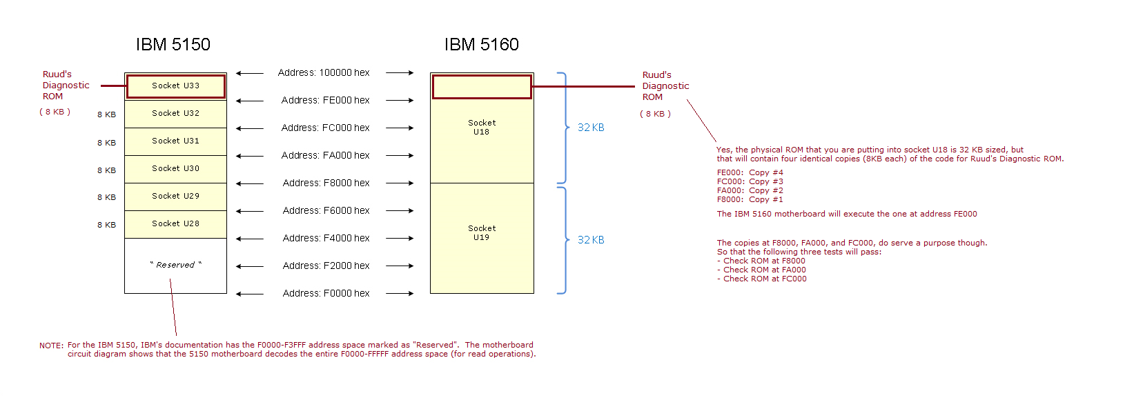
| Note 2 | Ruud's Diagnostic ROM is actually only 8 KB in size. To create a 32 KB sized image, the 8 KB image was simply quadrupled. Therefore, the 32 KB sized image contains 4 instances/copies of Ruud's Diagnostic ROM code. When the 32 KB sized EPROM is placed in socket U18, it will be the fourth instance that gets executed. A related diagram is at here. |
| Note 3 | Regarding the programming/writing of an image into the W27E257: Even though the W27E257 is an EEPROM, rather than a 'traditional' EPROM, you will still need an EPROM programmer (or other) to program/write to the W27E257. That is because the IBM 5160 motherboard does not support programming/writing to EEPROM's in its sockets. |
| Note 4 | It is possible for a RAM chip to fail in such a way that not all of its addresses are affected by the failure. |
| Note 5 | For most of its work, Ruud's Diagnostic ROM (RDR) needs some RAM for variables and for the stack. The motherboard RAM cannot be trusted (a common use of RDR being because there is bad RAM in bank 0). For that reason, RDR uses either: - If an MDA video card is present, the unused video RAM on that; or - If an CGA video card is present, the unused video RAM on that; or - If 4 KB of RAM at address A0000, some of that RAM. (Version 4.3 or later of RDR required.) - If 4 KB of RAM at address B0000, some of that RAM. - If 4 KB of RAM at address B8000, some of that RAM. |
| Note 6 | Some people may be puzzled as to why there is no mention of the checkpoints also being sent to I/O port 80h, the port monitored by an ISA POST card. Although this diagnostic does also send the checkpoints to I/O port 80h, rarely does an ISA POST card work in an IBM 5150 or 5160. Do not be surprised if it does not work. More information about that is at here. |