[Copyright 2002,2003,2004,2005,2007 Frank Durda IV, All Rights Reserved.
Mirroring of any material on this site in any form is expressly prohibited.
The official web site for this material is:  http://nemesis.lonestar.org
Contact this address for use clearances: clearance at nemesis.lonestar.org
Comments and queries to this address: web_reference at nemesis.lonestar.org]
The basic differences between the classes are shown in this table:
| Fixture Class (Ballast and Lamp type) | Starting or "Striking" Technique | Fixture Uses Starters? |
|---|---|---|
|
Pre-Heat
(See Section 5) |
Heated cathodes while starting | Yes |
|
Rapid-Start
(See Section 6) |
Continuously heated cathodes and ionization from fixture | Starter function integrated inside ballast |
|
Instant-Start
(See Section 7) |
High starting voltage, sometimes with ionization from fixture | No |
All fixtures have a fluorescent lamp and a ballast, but only the older "pre-heat" designs have a starter. Each of these three components is discussed in detail below.
Although the mercury is in liquid form when the lamp is not operating and the lamp is at room temperature, the mercury vaporizes (moving from the liquid phase into the gas phase) when the electrical flow through the argon gas starts, and the presence of gaseous mercury greatly increases the ultraviolet light produced. The mercury also helps increase the amount of current that can flow through the gas, and in turn that helps generate even more ultraviolet light.
(Mercury is a hazardous material if it escapes from the lamp. Additional information on mercury and other fluorescent lighting safety issues appear in Section 9.)
This ultraviolet light strikes a layer of phosphor that is coated on the inside of the fluorescent lamp, and in turn the phosphor blocks most of the ultraviolet light. Because of the ultraviolet light, the phosphor emits various frequencies of visible light. Manufacturers blend phosphors to produce various shades or colors of visible light. In some cases, the glass that the lamp tubing is made from is also tinted to provide the desired light color. Some manufacturers build fluorescent lamps that produce several shades of white as well as colors like red, yellow, blue and green. A discussion of lamp colors appears in Section 3.
Some phosphors are brighter than others, so depending on the materials used, a fluorescent lamp can produce different levels of light, despite consuming the same amount of electricity. Other design factors can affect the efficiency and life expectancy of a fluorescent lamp. Additional information on lamp efficiency appears in Section 8.
The phosphor absorbs most of the ultraviolet light, but some does escape from the fluorescent lamp, which is why plastic lenses and other components of fluorescent lighting fixtures sometimes gradually become yellow or brittle. Most of the paints and plastics used in fluorescent fixtures contain UV-inhibitors so that they don't wear out as quickly. However, this doesn't stop the leaked ultraviolet light from slowly damaging other objects in the area.
Fluorescent lamps that are meant for pre-heat and rapid-start fixtures contain filaments at each cathode. The filaments are usually made of tungsten, but other materials are used by various vendors. Lamps for Instant-start fixtures don't need a filament to heat, but may contain a filament in the cathode anyway. Sometimes, this is done because the filament material is better suited to donate electrons needed for the electrical arc through the gas in the lamp.
In addition, some ballasts contain a step-up or step-down transformer (or similar mechanism), increasing or lowering the voltage supplied to the lamps so that the same size lamps can be used regardless of the local electrical line voltage. A longer lamp needs a higher electrical voltage than a shorter lamp, and the power provided by the local electrical supply may not be the precise voltage that is needed to operate that size lamp.
For example, in the United States, ballasts are commonly sold for 120VAC and 277VAC (277VAC is used in commercial three-phase power systems), yet the same lamps can be used with either supply voltage because the ballast compensates for the difference in line voltage.
This means that the appropriate ballast that matches the available line voltage must always be used. To help prevent incorrect use, in the United States, ballasts for 277VAC electrical systems usually have red or pink labels while 120VAC ballasts have white or yellow labels.
In addition to matching the line voltage, a ballast must exactly match the type and number of lamps used. Each ballast is marked with the list of the sizes and number of lamps that the ballast can operate, along with a diagram showing how the lamps must be connected to the ballast. Connecting lamps larger than what the ballast supports may cause the lamps to malfunction or operate dimly, while lamps smaller than what the ballast allows will be able to draw too much current and can overheat. Either incorrect situation can also damage the ballast or cause a fire hazard.
As to the current-limiting function of the ballast, they only come in two types: Magnetic and Electronic.
Magnetic (sometimes called Inductive) ballasts contain an electrical choke, which is a specially wound coil of wire. Since electrical current flowing through a wire generates a changing magnetic field around the wire, and a changing magnetic field generates electrical current in wires within that magnetic field, a ballast uses these opposing magnetic forces to limit the amount of electrical current that can pass through the coils inside. As the current flow through the ballast increases, the coils inside the ballast generate a stronger magnetic field that opposes the flow of current that is trying to pass through the ballast to the lamps. This interaction achieves a balance and limits the total current flow to the lamps to a specific amperage.
In addition the current limiting, an additional set of windings may exist inside the ballst that step-up or step-down the line input voltage to the levels needed to operate the lamps. This may be a discrete transformer, or be integrated into the current limiting section of the ballast.
Rapid-Start ballasts are more complex, requiring additional lower voltage outputs to keep all filaments heated at all times, and to impress a high voltage electrical potential between lamp fixture and cathode voltages.
Because there is a transformer or similar magnetic coil inside the ballast that operates at 50 or 60Hz, it will generate a low frequency "hum" when operating. Depending on the quality of the materials in the ballast, the produced noise can be reduced, which is why ballasts have a "Sound Rating", with "A" considered the quietest ballast, and a "C" rating having far more noise. Even the "A" rating on a Magnetic ballast generates enough noise to prevent fluorescent lighting from being used in certain facilities, like broadcast or recording studios.
Note that some "home improvement" stores, in order to claim they have the lowest price, have started selling noiser ballasts, which are usually cheaper to make. Watch out for this when shopping. As of March 2005, Home Depot was found to be guilty of this in their 96T12 dual-lamp ballast offering, selling only sound rating "C" magnetic ballasts, or an Electronic "A" rated ballast for $25 more. Their competitors will sell you a better sound rating on an magnetic ballast for about the same price.
Also, improper or loose mounting of the ballast and fixture can act as a sounding board, increasing the noise levels further.
Magnetic ballasts have been around since fluorescent lighting was invented, which was around 1935.
Electronic (also called "solid state") ballasts contain semiconductors and
other electronic components. Electronic ballasts are like the switching
power supplies you find in computers, creating a chopped electrical current
with up to 50,000 pulses of electricity supplied to the lamps per second
instead of the 100 or 120 pulses per second produced by a magnetic ballast.
(In computers, that chopped power is eventually rectified and regulated to
the desired voltages needed by the computer.)
When the lamp is cold and an electronic ballast is being used, the pulses of current sent to the lamps by the ballast are more frequent or last longer, and as the lamp reaches the desired operating current consumption, the electronic ballast provides shorter or more infrequent pulses of current to the lamp. Solid state ballasts are a fairly recent innovation.
As with Magnetic ballasts, the Electronic ballast is more complicated in Rapid-Start fixtures, requiring additional lower voltage outputs to keep all filaments heated at all times, and to impress a high voltage difference between lamp fixture and cathode voltages. These voltages are obtained from additional sets of windings in the switching power supply transformer, in the same way that a computer switching power supply has multiple sets of windings and each set is used to produce a specific voltage required.
Electronic ballasts are more power-efficient than magnetic ballasts, are lighter, and can typically be squeezed into smaller spaces. Almost all compact fluorescent lamps use an electronic ballast.
Electronic ballasts have a further advantage in that they are virtually silent. They do not produce that low frequency "hum" produced by magnetic ballast fixtures. All electronic ballasts have a Sound Rating of "A", but they are actually quieter than a compatible magnetic ballast that also has a Sound Rating of "A". In fact, a fixture containing an electronic ballast actually does produce some noise because there still is a transformer inside the switching power supply in the ballast, but because it and the lamps operate at higher frequencies than found in a fixture with a magnetic ballast, what sound does escape the enclosure of an electronic ballast fixture is usually well above the human hearing range.
There are some negatives to electronic ballasts. They are currently a lot more expensive, they don't survive power surges and overloads or high temperatures as well magnetic ballasts, they can interfere with radio and television equipment due to emissions from the power switching electronics, and the higher flicker rate can interfere with infra-red remote control systems used in televisions, VCRs and other devices.
The X-10 remote control system can be rendered useless by some models of T-8 electronic ballasts on the same power distribution transformer, due to the interference the ballasts allow to leak onto the input power line. (I have not encountered any model of compact fluorescent lamps that have this problem, provided that the lamps are not at the end of their service life and are operating normally.)
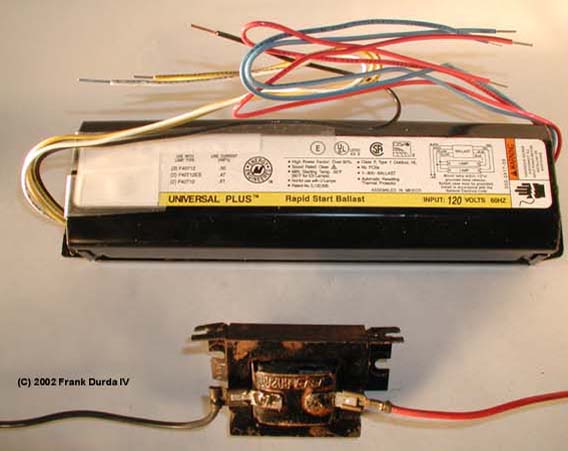
Two types of ballasts: (Top) A two-lamp rapid-start ballast for four-foot lamps. This is the most common ballast type made. (Bottom) An open-frame pre-heat start ballast used for a single 18" lamp. (The ballast shown came out of a clothes dryer.)
As current continues to flow through gas in the starter, the gas in the starter heats and starts to bend one of the metal contacts inside, in the same way that a bi-metal thermostat works. When sufficiently heated, the bi-metal moves out of position and creates a direct electrical circuit in the starter. Now, the maximum amount of current flows through the filaments of the fluorescent lamp, which heats the gas in the fluorescent lamp.
Meanwhile, because electricity is not arcing through the gas in the starter, the starter is cooling and eventually the bi-metal contact will begin bending back to its rest position. At some point the two electrical contacts stop touching and now the electricity has no place to flow except through the gas in the fluorescent lamp, or the gas in the starter bulb. If the fluorescent lamp was sufficiently heated, its resistance will be lower than the resistance of the gas in the starter, so electricity will begin arcing through the fluorescent lamp. (The starter is deliberately designed to have a higher break-down voltage than the much-longer fluorescent lamp. The starter also has the resistance of the two filaments in the fluorescent lamp as part its electrical circuit.)
Once the fluorescent lamp successfully starts, the starter bulb continues to cool and eventually the bi-metal contact returns to its "rest" position.
Some starters also contain a capacitor (also known as a condenser) that can reduce electrical noise and assist in the starting process.
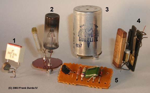
Various types of starters used in pre-heat systems: (1) A semiconductor starter and capacitor from a compact fluorescent lamp, (2) A glow-blub starter and capacitor, (3) a glow-bulb starter in its metal can (note the small hole in the top used to see the glow lamp in operation), (4) A manual reset starter with capacitor (very old), (5) An electronic starter from a four-foot fluorescent lamp "shop light" fixture.
Like the main fluorescent lamp, glow bulb starters eventually wear-out and must be replaced. Most manufacturers recommend replacing the starter when the fluorescent lamps are replaced. A chart that shows which size of lamp is used with each type of starter can be found in Appendix A.
In some fixtures, particularly some compact fluorescent lamps, the starter is electronic and does not need replacing or cannot be replaced.
Rapid-Start fixtures have circuitry inside the ballast that handle the starting process. Instant-Start fixtures use high starting voltages to overcome the higher electrical resistance of a cold fluorescent lamp.
For example, a four-foot T12 lamp typically is rated to consume 40 watts of power. This is the case regardless of the line (or "mains") voltage supplied to the ballast. A fixture with two of these lamps would consume around 80 watts of power, and so on.
Amperage consumption is usually stated on the ballast, but this number must be used in conjunction with the line voltage value. For example, a 120V 60Hz ballast will show a higher amperage value than a 277V 60Hz ballast operating the same two lamps. This is a normal artifact of electricity, in that as the voltage goes up, the current demand usually drops, while providing the same amount of work force (watts).
A rapid-start ballast meant to operate two 40 watt lamps that is supplied with 120 volts will show a current rating of about 0.8 amps on the ballast case. (The two lamps combined consume around 0.66 to 0.7 amps.) Solid state ballasts will be usually show a slightly lower current rating as they are usually more efficient and dissipate less power as waste heat. The power consumption of the same size and type of ballast will vary between models and manufacturers, depending on the efficiency of the design and manufacturing tolerances of both ballast and lamps.
Note that if your line voltage is only 115 VAC or 118 VAC, the ballast will draw more current than the amperage value stated for a line voltage of 120 VAC.
The actual power consumption of a fixture will typically be higher than the figure listed on the ballasts during the period when the lamps are starting, or if the operating environment is cold. As the lamps warm up, they become more efficient.
As with all electrical circuits, maximum loading should be determined by a licensed electrician. Initial in-rush and other factors must be considered when determining the maximum load that can be placed on any branch circuit, and that total must always be less than the rating of the circuit and its wiring.
Appendix A: Fluorescent Lamp Replaceable Starter Size Table (HTML)
Section 3: Fluorescent Lamp Colors, Shapes and Sizes (HTML) [NEXT]
Return to The Fluorescent Lighting Reference Index (HTML)
[Copyright 2002,2003,2004,2005,2007 Frank Durda IV, All Rights Reserved.
Mirroring of any material on this site in any form is expressly prohibited.
The official web site for this material is:  http://nemesis.lonestar.org
Contact this address for use clearances: clearance at nemesis.lonestar.org
Comments and queries to this address: web_reference at nemesis.lonestar.org]
Visit the nemesis.lonestar.org home page and index
![]()