|
Local copy of uCode, Release
Patches, Feature Patches (before IBM cleanses the
site!) IBM 5494 Remote Control Unit
Brochure CO2V4002 5494 Maintenance Information Related
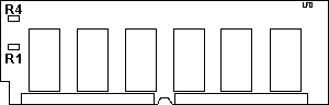
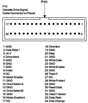
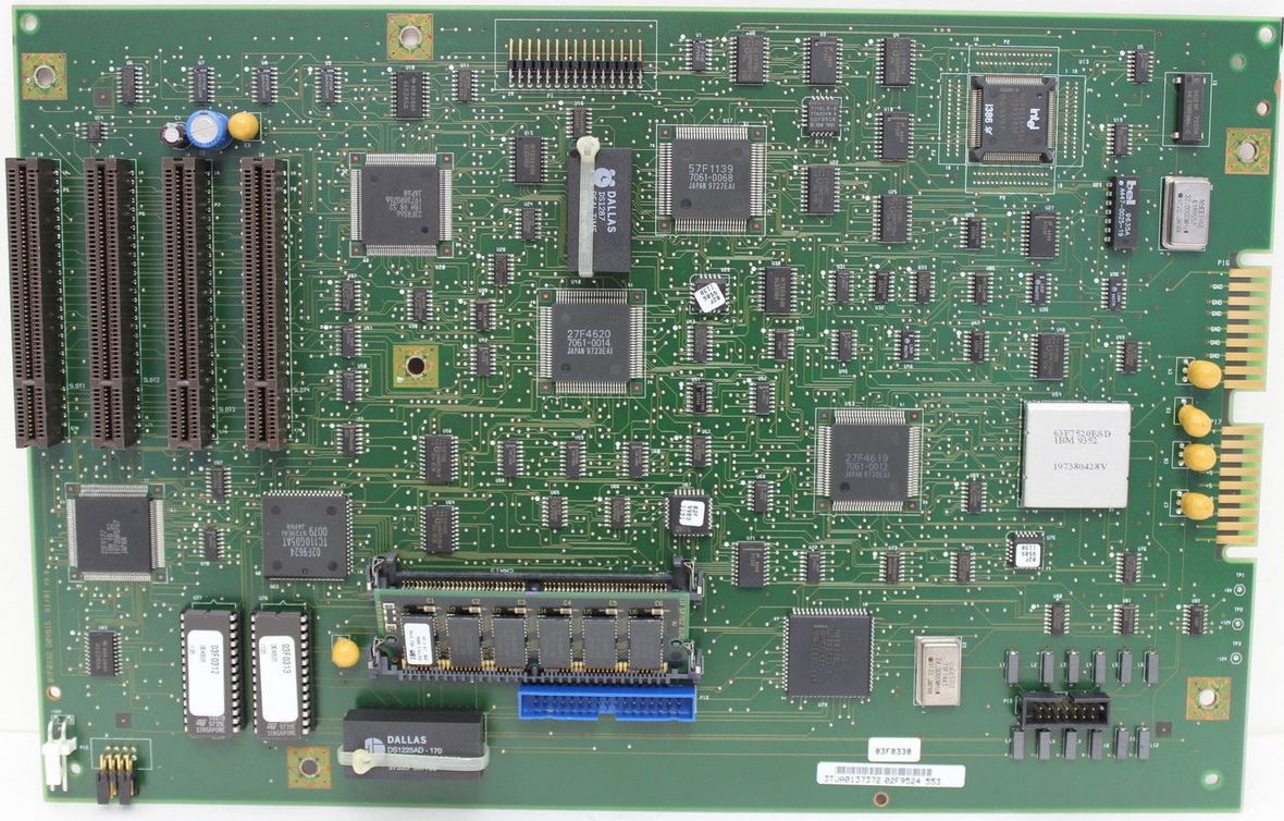
Redbooks 5494 Planar P12
Floppy Controller Header Pinout P13 Operator Panel Controller Pinout
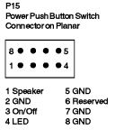
P15
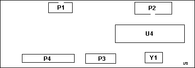
Speaker/Switch Assembly Pinout 5494 Front 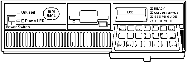 5494 Planar 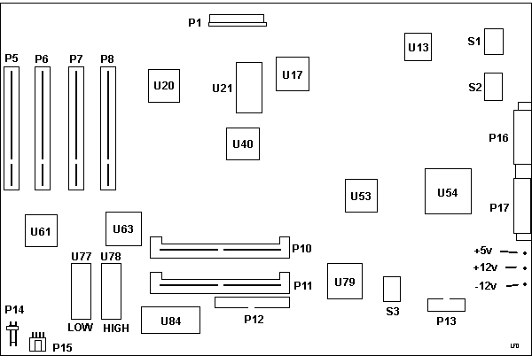
2MB
ECC?? SIMM, 53F7913 Operator Panel Controller Board
P12 Floppy Controller Header
Pinout P13 Operator Panel Controller Pinout 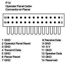 P15
Speaker/Switch Assembly Pinout
KRON (?) 55JET064 Global Manufacturers' Services
Valencia, Spain Uses a Model 90 form factor PSU, but
wimpier . No HD power plugs. Uses an NMB Boxer fan, 3610NL-04W-B10 12v, 0.13A ball
bearings, brushless 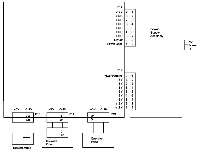
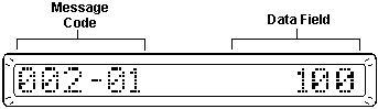
5494 Floppy 52G3400 / PN 10H4267. 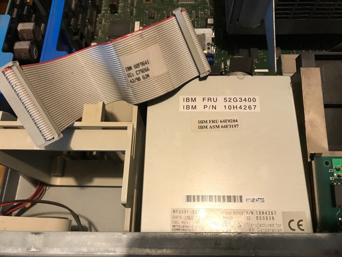 Stefan Lemanski snagged a 5494 and is presently looking into it, quite literally... NOTE 64F0204 / 64F3197 BUT it has the Mitsubishi MF356F-822MB "*" floppy. In IBM's eyes, there's no need for more than a one device cable... Bay B has the LCD display, Bay D has the "glove box" Bay C is inaccessible. Why waste good money on even a twist? There can only be one... floppy [Highlander]. Why use a three-device cable like the Model 90 if you will only be able to use one device... ever... Note that the 5494 does have the Adapter Card-Guide Assembly 33F8363. It does not have the 92mm Base Fan. 5494 Operator Panel Components The operator panel consists of a keypad, an LCD, and four LEDs (Ready, Call 5494 Service, See PD Guide, and Test Mode) that indicate operating status. An 8051 controls the LCD, LEDs, and the keypad. Communications between planar and operator panel are through a serial port. LCD If an error occurs before or during normal
operation, both a message code and an SRC will be
displayed on the LCD and an LED will be lit. If more
than one error occurs during normal operation, the
message codes and SRCs will cycle at 3-second intervals.
If the error clears (a link is established after a
failure, for example), the message code and SRC will be
removed from the LCD by the 5494. Normal Power-On Display Sequence Soon after the 5494 power pushbutton is set to ON (|): 1. All LEDs are ON for 1 second. 2. All LEDs are OFF for 1 second. 3. The Test Mode LED is switched ON. 4. 001-01 is displayed, indicating that POST is running. 5. The date and time are displayed on the LCD. 6. The microcode is loaded. 7. The Test Mode LED is switched OFF. 8. Within 10 seconds, the Ready LED is switched ON Keypad Description 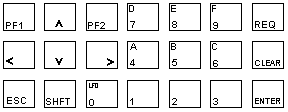
The keys on the keypad allow commands to be entered and sent to the 5494, and include: REQ Initiates a
request function If you hose the refstamp, the 5494 will not boot up and the error code '003-04 1' is displayed on the Op Panel. Model Conversions Cables For 5494 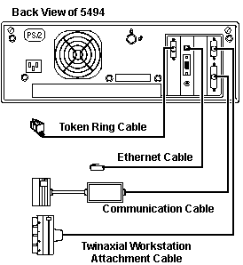
72X5645 Cable Asm,Twinaxial Workstation Adapter
(Ports 0-3) Note: The Twinaxial Workstation Attachment cable
connected to the lowest number slot supports
twinaxial ports 0--3. The Twinaxial Expansion
Adapter, if installed, supports twinaxial ports
4--7. |