|
7677diag.exe 76/77 Diagnostics Diskette G7jt61a.exe 76/77 BIOS revision build 61A 7677dosd IBM Enhanced Local Bus Dos/Win 3.1 driver disk S3 928 Windows 95 drivers disk Win95-Setup for S3-928 to PeterWendt's site S3 86C928 GUI Accelerator 202 pages Datasheet / Programming Alfred Arnold's VRM Hack Local Copy original HERE LT1085 VRM, 1N4001 Diode, a 200k trim pot, and look at his story... 35 / 56 / 76 Power Supply Lacuna Planar IDE Devices
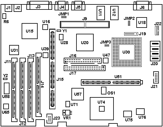
Lacuna Planar (76/77 i/s)
JMP1 is the Power-On Password jumper. The POP can be cleared by moving the jumper to the other set of pins, then powering on. After power on, you can leave the jumper on the pins that you moved it to. JMP2 is the Privileged Access Password jumper. Locked State: jumper across middle pin - pin 1 PAP cannot be set, changed, or removed. Change State:- jumper across pin 0 - middle pin PAP can be set, changed, or removed. My humble suggestion - DON'T SET THE PAP! If you forget the PAP, only the last saved configuration is valid. You will never be able to successfully change the configuration again. The PAP function involves writing the state to an unknown area of the NVRAM and another memory chip. If the PAP is dorked, for all intents the planar is hosed. Memory Supported
4MB, 8MB and 16MB 70-nS SIMMs, Parity or ECC Flash Disk, Build 61A The 7677 FLASH Disk is for the Lacuna planar. Older Model 76 and 77 have the Bermuda planar which does *not* have FLASH BIOS. Flash Revision 03 - original release 04 contains the following enhancements: 05 - contains the following enhancements: 07 - ? 08 - ? Fixes "IRQ 00 Not Being Serviced" Errors In
Error Log Charles Lasitter Peter Wendt Jim Shorney Can't
Access System Partition on 76s (maybe others)
The 76i / 77i are "non-IML" machines and do not support a "real system partition" anyway - they just offer the ability to "park" the reference and diagnostic disk for easier access on the harddisk. Otherwise called a Convenience partition. Ed. But they DO support a Convenience Partition IF you use an IBM SCSI adapter (NOT the FD SCSI-2 that is standard). To install a Convenience Partition and be able to access it, you have to LLF the drive and then restore the partition. Just running "Restore System Partition" without LLFing the drive first will result in the system refusing to access the partition. I have a Fast/Wide in my 77s, and I can bring up the Convenience partition with F1. So much better when you have a huge pile of poorly titled or untitled floppies on your desk... However: I had similar problems getting a
system partition on the drive. There had been one once
on your drive (the unused 4MB space) but it has been
loused up by what reason - same what happened to me. In
this case the MBR of this "hidden" partition is invalid
and cannot be used any longer. Therefore "Restore system
partition" does not work. The only way to get it back is
in fact a Low-Level format. In fact the order is
important. You need to install the system partition
first, *then* run FDISK from any other operating system.
Some FDISKs (like that from OS/2 2.x) do not always
accept the "system partition" as hidden ... :-) ... and
simply overwrite it or corrupt the boot / MBR
information. OS/2 2.1 CID installation was famed for
lousing up the system partition on the 76i / 77i.
My recommendation: If you already
have a lot stuff on the drive - leave it as it is. If
you'd only installed the Win95 so far - mind running the
LLFORMAT and install a system partition. You need to
start with the reference in A: and press CTRL+A in the
main menu to start (A)dvanced Diagnostic. Then run
"Format harddisk" and follow the instructions on the
screen. Reboot after finish - restart with the reference
disk and run "Restore system partition". Worked fine
when I tried it last time ... Processor Upgrade Installing
a 5V Upgrade CPU Installing
an 83 or 63 MHz Pentium Overdrive Processor
Installing
a 3.45V Upgrade CPU VRM FRU
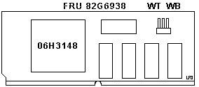
06H3011 / PN 06H3010
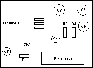
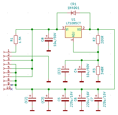
Ed. From the closeness of the solder pads, I'd guess C1, 2, and 3 are 10u / 50v caps. IBM close not to populate them for whatever reason. Bean counters? Jim Shorney says: NOTE: Don't substitute a 'close' standard value for R3. If you don't have access to the exact value; a 300 ohm resistor in series with a 100 ohm trimpot could be substituted for R3 to allow fine trim of the regulator voltage. The formula for calculating the resistors is in the regulator data sheet. Use the simpler formula that ignores reference current. LT1085CT Datasheet
LT1085 3A Low Dropout Positive Adjustable
Regulator Interposer
From Tam Thi Pham
NOTE: Some systems
do NOT accept ANY L2 cache modules. I have three
Lacunas, none of them supported any of the IBM marked
modules or IDT modules. Other people (Bob Watts among
others) just seem to drop a POD in their machine, toss
in any old L2 module, and it comes up happy. It is NOT
the fault of the interposer. Read below for
details. Dirty Secrets of the POD From Peter Wendt The whole Pentium Overdrive debacle was a mess from the beginning, with Intel changing specs and making motherboard manufacturer's and BIOS writers crazy. And Louis tried every BIOS level and revision I'm sure. In fact they changed the PODP specs shortly before announcement. This L2 communication problem shows up on all these machines where the design work starts in early 1993. At IBM these are namely the PC-300 and the "Lacuna". In a way the PODP was the Edsel of the processors: good idea, bad marketing - and outdated in the right after announcement. Intel hurried it a bit - when the problems showed up the major work was already done for the board-makers. The main reason AFAIK: the original concept did not include boards with L2 WB-cache.... the most of the older boards did not have L2 - and if, then it were simple WT-cache. The problem got sharpened with the introduction of the "COAST" specification originally designed for "real Pentiums", when it got adopted by the 486/POPD developers. Good example: the PS/VP Series 2. A straight 486-board with cache SIMM. That wasn't planned that way. IDE
Devices The interrupt request (IRQ) of an IDE interface was designed to be on a non-shared interrupt level. According to PS/2 Micro Channel* system architecture, all hardfile IRQs are shared on interrupt level 14. In a Micro Channel computer system that supports both an IDE hardfile and a SCSI hardfile, a problem arises. The essence of the problem is that because the IDE interface IRQ was designed to be non-sharing, no IRQ "indicator bit" exists in any of the IDE status registers. In order for interrupt handling software to determine which of two or more devices sharing an IRQ level is the requesting device, an IRQ "indicator bit" or status bit is needed. The Figure shows a simple solution to provide the IRQ "indicator bit". To provide the IRQ "indicator bit" for the
Micro Channel IDE interface, bit 2 of port 92 was
selected. In previous systems bit 2 (port 92) was
connected to a pin in the I/O controller chip called
SECURITY OVERRIDE. SECURITY OVERRIDE is a signal
that can be mechanically jumpered to ground by a
customer engineer to override and reset the system
password. It sets port 92 bit 2 which is read by
POST during system power-up initialization. In normal functional operation, SECURITY OVERRIDE
is a static signal tied to +5V. Because SECURITY
OVERRIDE will only be jumpered to ground in the unlikely
and infrequent case of a customer engineer making a
repair to a PS/2 system, bit 2 of port 92 is multiplexed
to monitor the IDE IRQ14 line and serve as the needed
"indicator bit" as shown in the Figure. The enable
for the multiplexer is bit 4 of port E3 which is an
output (ROM_PAGE) from the memory controller. During POST initialization, bit 4 of port E3 is set to 0, and the SECURITY OVERRIDE signal is selected and its polarity can be read from bit 2 of port 92. After the necessary testing and initializations have been done, bit 4 in port E3 is set to a 1 before exiting POST. IDE IRQ14 is then selected through the mux shown in the Figure and latched with a free-running clock into bit 2 of port 92. Bit 2 of port 92 then functions as the IDE IRQ "indicator bit". IDE
CDROM on 76/77 i/s CONFIG.SYS: DEVICE=BTCDROM.SYS /D:MSCD001 Morten Kristensen I used these to run a WD2540 in 32 bit mode Same as above, Manual installation. Standard IDE/ESDI HD Controller Though others have successfully used the Busmaster IDE HD controller. When I set up the 540, it was for an ISA/PCI machine with built-in IDE controller. I was looking for as much compatibility as possible. Maxtor
10.2 GB IDE Under 98 First I tried to use FDISK, (the latest version, that supports 32 bit), but it would not allow me a partition bigger than 7.23 gig or something like that. I do not know the reason for this. Anyway, the max blast program worked great- I got the whole 10.2 gig (which was the primary reason for going to win98 anyway- 95a does not support a 32 bit FAT). As I said, once I got it set up properly on IRQ 14, It ran in protected mode with the windows driver. From Ron Doran From Peter IDE ZIP
+ Lacuna ( IDE ) For further information, an IDE CD-ROM device was previously on this cable, and it is jumpered as Master, and the ZIP drive is jumpered as Slave. Also, an IBM 0662 1 gig SCSI drive is the boot drive, on the factory installed Future Domain controller. Boot
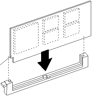
Sequence The IDE-channel accepts two devices in the usual master / slave configuration on a standard IDE-cable. There is however some care required if you want to use it simultaneously with the SCSI adapter. You need to set the boot-sequence in the "features" properly - to avoid problems when the system tries to boot from an IDE CD-ROM ... :-) IDE Planar Header Luckily, I found a non-polarized plug (no keys
at all). All you ISA/PCI veterans know what to do if the
system refuses to boot- check the
cable pin 1... (I just turned the cable 180,
plugged it in, and it booted). If you do not have the uncommon dual key plug, simply use a file or a sharp knife and remove the polarizing key off an IDE cable you have laying around. Note that Pin 1 is toward the riser! Look at the planar illustration. The red marked wire goes toward the riser! From Dr. Jim Pin One Makes a Difference
I had the drive set as master, but what
ever I did, 3 different cables 3 different IDE CD's.
Another planner. Nothing would work. Damn drive door
wouldn't even open. I was looking at the planner and it hit
me. I had assumed that pin 1 for the IDE port was on the
same end as the FDD cable. I noticed one of the middle
pins that was cut for use of a cable the was plugged to
act as a key. I had been hooking up the cable on the planer backwards all the time! So note pin one for the IDE is towards the riser card. IDE Controller Capabilities
IDE CDR
Peter responds If you don't have a HD on the IDE port: jumper the CD-burner as "Master". The IDE port often dislikes the use of a "Slave only" configuration. And check your systems' BIOS level. Those before 07 had several limitations on the type of supported devices / drive sizes. Take 08 at least.
Video S3
928 Video Drivers S3-928
Trivia 2. The S3-928 cannot be disabled physically. It goes in
some sort of "sleep mode" when another VGA / SVGA
capable card is detected - nonetheless parts of the card
is still activated and *may* cause trouble. Not confirmed: the early BIOS releases below 07 seem to be more vulnerable to video disturbances with S3 and other video cards. One thing IBM tried to fix with 07. In either case you better use a BIOS 08 - also for the "over 524MB HD" capability. 3. The XGA-2 card has not been announced to be used with the "Lacuna" series anyway. IBM seems to have removed the card from the list, because in the first announcement of the 76i / 77i the XGA-2 is still listed - not in the later product / option matrices and product descriptions on the "Lacuna". 4. The 9515 and 9517 monitors are not 800 x 600 capable
*per IBM*. They can be tweaked to show an 800 x 600 like
picture, but it is distorted and the monitors have no
explicit mode for it. These screens are "XGA-2 only"
Multi-Mode screens with fixed adjusted presets. They are
no Multisyncs. If you want to run the Lacuna with most of the possible modes switch to a 9525 or 9527 monitor. Or any other good SVGA screen. I run my "workhorse" 9595-S30 with XGA-2 on an Eizo F35, the 9577-BTG runs with a NEC 15XE and both do fine. 5. Nonetheless the XGA-2 (at least) will run in a Lacuna. There might be some interference to clear out manually during OS installs, which is the primary video system. This is usually the one with the monitor attached. In 99% of all cases OS'es get that right - but sometimes the onboard video is ranked higher and the OS gets confused. (Haven't seen that too often to be true - but can happen). 800x640x64k
under W95 AVE
Slot Video Adapters under W95
>I have a 77s that has displayed a charming
quirk- it waves the top half inch of the screen. Not all
the time, but... Please check the Video RAMDAC type and origin of
the S3 chip. Some Thailand-S3s have internal bugs using
an earlier stepping mask. The RAMDAC should be the
AT&T in this case. These were the machines that
cause massive faults under OS/2 2.1 ... The S3 chips are famed for a lot "undocumented features" (like using an address for COM4 (? yes - think so)) and this chipset is -basically- a VESA Local Bus chipset which is stitched in the Lacuna planar with a hot needle. >IIRC, the last three digits of one of the S3's I/O ports is 2e8. Like B2e8h or something. Yep. That was it. >If I understand this correctly, it wasn't S3's fault that some com port hardware did faulty address decoding. Yes and No. On MCA it wouldn't have been too bad, because MCA *should* use a full decoding (or: 24 bits at least, 16 bit for the I/O range), but -again- the VLB chipset was a little buggy already, before IBM decided to put that on a MCA platform. Who's to blame ? S3 -in addition- delivered chipsets which were out of specs for some series which made things worse than it already was. >The workaround was to not use com4/2e8 if possible, or to remap com4 to a different address if it was really needed. IBM's COM3 - 4 ports on the PS/2 were not "XT-style" so this COM/Video interference wasn't much of a problem here. It was *much* worse on the "Rocket" PS/VP Series 3, which were PCI/ISA with more generic layout and addresses. They used S3 chipsets too ... >I have seen Lacunas with S3-928 Rev. G and Rev.
P. Seen both kind with either a BT or
AT&T DAC also. Most likely the -G- revisions are afflicted by what IBM
euphemistically called "video timing glitch" ... which
cause the entire machine to crash under OS/2. IBM
offered various bug-fixes for OS/2 2.1 and tried to fix
the problem with modified hardware as well, which lead
to slight incompatibilities with driver versions. The
drivers for the original (un-fixed) 2.1 did not work
very well with these machines. The APARs offered for
Germany were.... now... not so good. The US-APARs seem
to be better, but you should not mix different language
versions within any OS. The later series of the "Lacuna"
seemed to be more stable and especially with OS/2 Warp
the problems rarely occurred. Some machines that have been migrated to Win95
show up odd effects recently. Especially when switching
to and from DOS-boxes into full-screen hi-res modes may
cause the system to hang, fall into GPF or show odd
colored icons / missing icons / speckled screen etc.
This seems to be caused by a faulty, out-of-time palette
read ... haven't noticed that on my machine, so I guess
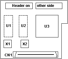
the -P- level of the S3 seems to be stabilized. CN1 Male 68 pin
VMB mediabst.exe
DOS/Windows drivers U3 is a Vialogic PowerPlay 32 (3 Squared) MediaBurst Movie Adapter expands up to four times the window size of many software motion-video compression algorithms, such as Video for Windows or Ultimotion(TM), and provides access to the VESA Media Channel (VMC) The MediaBurst Movie device driver uses the PowerPlay 32 video accelerator chip to provide enhanced playback of digital video. This allows viewing of video clips in larger-sized windows or full-screen without the degradation in speed and picture quality usually associated with software motion video. Key features of the MediaBurst Movie option
include: RESOLUTION SUPPORTED BY MEDIABURST OPTION My thanks to Brad Parker for ripping apart his 77s and
sending me a scan. Parallel Port ECP
Support From Peter That should fix the problem. The 9577 -as
most PS/2- has a "DMA-arbitrated" LPT-port, which is
neither ECP nor EPP, only "sort of". The "Disable"
directs the machine not to use DMA during bi-directional
transfers and use a contiguous data-stream. The DMA-mode tends to miss backcoming signals from PP-devices especially PP CD-ROMs, Tapes and Zip-Drives. Some printer-drivers use the bi-directional communication to signal details from the printer back to the computer Direct
Connection under W95 For a detailed description of the DCC process, 95 to 95, 95 to 3.1x, etc. check out Connect Pages at Kime.Net. Parallel
Port "!" under W95 with Audiovation Cache Modules Compatable
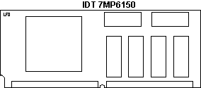
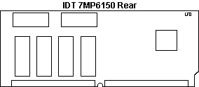
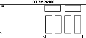
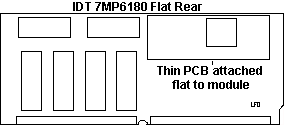
Cache Sources Sorry.. let me be more clear! Here are *all* the IDT modules I know
about: Installing
Cache Module
L2 Cache Modules There has been a number of efforts to deduce the proper choice of WT/WB with certain processors. But if you search the newsgroup, some boards work one way, then move the CPU and cache to another board, and it bombs. Whatever works for you ....
Overclocking the Lacuna board From Zp Gu This mod is relatively easy. I changed the 66.667mhz OSC to an 80mhz surface mount crystal/osc from Digikey and the board is now running an AMD-133 at 160mhz without any problem. The board actually has 4 thru-holes under the OSC, but IBM chose to put an SMD instead of a half size socket. Socket would have made life much easier. I didn't attempt to put a socket there since I don't have the right equipment/skill to do so. I just soldered a surface mount 80Mhz to its place. Putting a POD83 in failed POST. I can't imagine Intel being so tight on this, but maybe it's just my bad luck. Running it at 83mhz was no problem. From Peter Wendt The effect was much worser with the
Kingston Turbochip - but also noticeable with the
original DX4-100 ... where in addition the VRM turned
really hot ! Significantly hotter than under normal
operation - a sign that the power drawn from the DX4 at
40MHz is "a little bit" higher than at 33MHz. I had only a "full size" oscillator
and needed to build a sort of "adapter" from half-size
holes to full-size socket. But that's a minor problem.
*Then* I needed to solder an adapter for the original
66.6667MHz SMD-crystal ... Aaak ! Anyone tried that modification with a "Bermuda" ? These have MCA XGA-2 cards and no "local bus video" as the "Lacuna". Should work a bit better there ... probably. From Zp Gu From Peter Wendt
Early Lacuna Streaming Limitations LanStreamer and EtherStreamer adapter don't work in 76i/77i with 25MHz planar (FRU P/N 95G9691) Streaming mode adapter cards are not supported for use with 76i/77i systems fitted with 25MHz planar. The problem is caused by a limitation of the level of Bus Interface Controller chip used on this planar. Replace the systemboard FRU P/N 95G9691 with FRU P/N 96G1305. (Identification - 95G9691 = 'yellow' / 96G1305 = 'blue' Synchro Stream Controller. Peter said: The 25MHz boards are afflicted by a flaw
in the "Synchro Stream" controller: a large yellow or
blue chip somewhere in the middle of the board. If
yours is P/N 95G9691 and has the yellow synchro-stream
controller it might not work with the faster network
adapters of the IBM Streamer series. If it is P/N
96G1305 and has the blue synchro-stream controller it is
not afflicted by this misbehaviour. In "normal life"
this has no affect however - you only will take notice
if you use adapters that use the 80MB/s high speed data
streaming. Speaker Noise From Peter When the Lacunas came out there was a series of falsely wired "speaker /power switch / LED" units - which had the speaker wired to +5VDC of the HD activity LED instead to GND. Now - these machines made a lot noise when accessing the harddisk :-) |