8550/70 756x Power
Power Supply Pinout
Test PSU
7561 / 62 PSU Specs
8570 PSU Specs
8550 / 50z PSU Specs
Remove PSU
Remove 8570 PSU   

8550 Power Connector Hack   [David Beem]
8570 Power Connector Hack   [Peter Wendt and Major Tom]


Power Supply Pinout
   Same for 8550 (94w), 8570 (132w) and 756x (180W). 

Top row, odd numbered pins, left to right, 1-49
Bottom row, even numbered pins, left to right, 2-50

All even pins 2-48 are DC Return (Ground)
Pin 1 is -12v DC
Odd pins 3-13 are +15v DC
Odd pins 15-47 are +5v DC
Pin 49 is System Status
Pin 50 is Power Good

Test PSU

  Power-off the system. Remove power supply and place it with connector facing up. Power-on the power supply and check for voltages listed below. If voltages are not correct, check the power cord for continuity. If power cord is good, replace the power supply.

NOTE: Sometimes AC power cords develop a set in the plug contacts so that there is intermittent or poor contact with the AC receptacle pins in the PSU. Try reseating or swapping out the AC cord.


Vdc Min

Vdc Max

Gnd (-) Pin

Pos (+) Pin

-9.0

-15.0

2

1

+9.0

+15.0

2

3

+3.7

+6.2

2

15


NOTE: If you have a dead PSU with no voltages, suspect F1 or F2 have blown.


7561/62 PSU P/N 33F5202 FRU 57F2728
  Made by Plessey in Italy.... 
Input 95-120v @ 3.6A 50-60Hz, 200-240v @ 1.9A 50-60Hz
Output (dc):
 +5v  25.6A
+12v  3.3A
-12v  1A
Battery Charger 26v dc @ 40mA

  This PSU has an external, two pin Molex connector that provides power to the case fan. There is a 9.25"Wx1.75"H inch hinged cover on the lower outer side of the psu. It is fastened at the front by a single captive standard screw. The cover pivots open on the rear hinges, revealing a three pin Molex power connector, like a female drive power connector. The battery cavity is 1.875" deep.


8570 PSU
   ASTEC, Model AA15530, IBM PN 90X9409, FRU 90X8626. Max continuous output power is 132 watts for the 8570 PSU.

8570 Voltage per Pin
Voltage (DC V)        Pin #           Current/Pin (mA)
-12                     1                  300
+12                 3,5,7,9,11,13          535
 +5                 15-47 Odd #s only     1130
DC Return           2-48 Even #s only      915
System Status           49                 ---
Pwr Good               50                 ---


8550/Z PSU
Rich Wolos keeps me honest 
   The original one coming with Mod 50.50z was rated 94 watts, no fan. HMM says part number is [90x9366]. (Ed. He's right, I remember the fan assembly that slides in at the back of the case. Old age, I guess...) 

MODEL NO.:  AA13621 IBM  P/N:    90X9527 IBM FRU P/N: 90x9366 

VOLTAGE           PIN NO.          CURRENT/PIN (mA)
-12V                1                 410
+12V            3,5,7,9,11,13         350
+5V             15-47 ODD NO. ONLY    760
DC RTN          2-48 EVEN NO. ONLY    640
SYSTEM STATUS       49               ---
POWER GOOD          50                ---

Max continuous output power is 94 W. 

   This is from a 50Z.  No side blower.  (The blower plugs into the motherboard, is supported by two plastic snaps to top rack, and it blows out the rear of the 50/50z unit). CASE BOTTOM of power supply does not have a screen, it has finely punched holes, 11 or 10 holes across, the length of power supply. 
     Cases vary color, gold/silver.  Security torx, 5 on side 2 on top. Like unto Mod 70 supplies, except no side blower, and lower rating. 


Remove the Power Supply (8550 / 50z / 70 similar)
   Remove the two screws at the back of the case. Remove the screw at the front inner corner. Pull PS out from planar. 
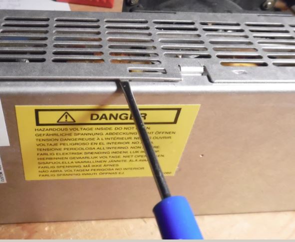
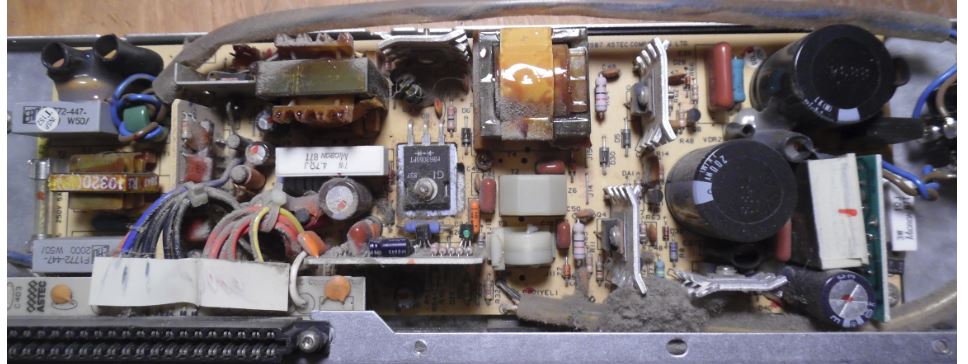
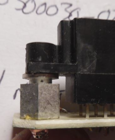
Power Supply Cleaning
 
8550 / 50z (No Built-In Fan)
   The way the 50 / 50z PSUs were built, they have a screen across the bottom side. Just like on a clothes dryer, you have to remove "lint" from the screen. I used a T-10 security Torx to open it.The fan is a Panaflow DC Brushless, Model FBH-09A12L, 12v 0.14A or a Nidec Beta SL Model D09B-12PLL 12v .09A


8570 PSU Removal and Cleaning (Built-In Fan)
  
Remove the standard screw at the front of the PSU. IBM even put a nice access hole through the drive shelf so you can get to it while the system is assembled.

Remove the two standard screws at the back [they pull the PSU back onto the rear of the unit]

With those three standard screws out, the PSU slides out horizontally, off of the planar power connector edgecard.

To open, get a security T15 Torx bit (tip is drilled out to mate with pin), remove the Torx screws. One Torx screw at the upper rear inner side has a toothed lock washer.


To undo the mating clam shell, note the retaining rib top center. Use a small screwdriver to get under the sheetmetal and pull the halves apart. The inner cover with the fan pivots on tabs at the lower inner side.


The fan is still connected to a power tap. Pull the cable straight out and the fan/cover is now free. Put aside.


I had a dust bunny about the size of your pinkie, jammed under a cable... Dust coated about half of the components. Can of cheapo Radio Schlock computer duster cleaned off the components, although I had to stop and let it warm up before proceeding...


You can pivot the edgecard connector out of the bottom edge of the PSU by SIMMply pulling UP at the rear of it, and then BACK on it.


Oddly, the two security T10 screws on the black plastic only seem to tighten the connector onto the post, leaving the edgecard connector free to move in four directions, but it's mounting does not allow it to pull out or be pushed in. Makes sense, this allows for greater freedom during automated assembly.

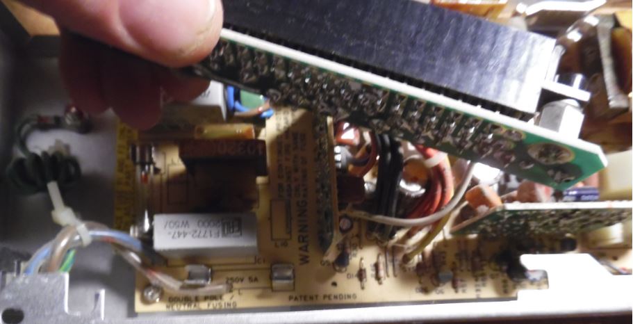
Once you pull the edgecard connector free, you will see F1 and F2 in the lower left corner of the PSU PCB (toward the AC socket). The power supply has TWO fuses, one on the Hot, the other on the Neutral. ASTEC called it "Double Pole / Neutral Fusing". ASTEC part number is ASTEC 084-00300030-0217. It is a BEL 3AG, 5A 250V Fast Blow.

Current BEL product is 3AG 5-R 3AG is a 6x32mm cartridge form.
http://belfuse.com/pdfs/3AG.pdf


8570 / 8550 Bus Riser Power Hack FRU 90X1111
 Original HERE  

You will need:

  • a soldering iron (a good one - not one for plumbers !)
  • a multimeter with VDC and Ohms-range
  • a standard power-connector (4 pins - maybe cut from a wrecked power supply)
  • a hot-glue pistol with some glue-sticks
  • some self-confidence (like always)

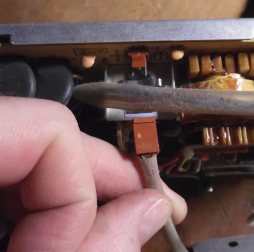
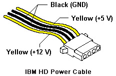
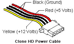
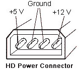
It is a good idea to leave the cables on the power connector as long as possible to make it fit on either direction a hard-disk can be installed in a Model 50 or 70.

Hard Drive Power Cables and Hard Drive Power Connectors 


   Please note that clone PC power cables use yellow/black/red, while IBM systems use yellow/black, or red/black/blue. What is important is the position of the conductor. Note that the drive power connector is keyed with beveled edges.

Riser Card FRU 90X1111 [assist from Major Tom]
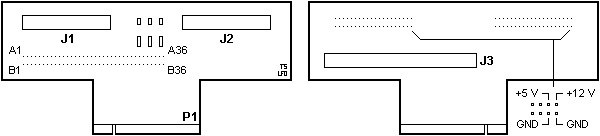
J1 (JN1) Floppy 1 (A:)
J2 (JN2) Floppy 2 (B:)
J3 DBA Hard-Drive Interface (pinout)

   The three resistor/capacitor pairs on the riser are for DC-buffering and decoupling. The earlier risers lacked them and once you'd stuffed in 2 FDDs or 1 FDD and a tape problems occurred with loss of data during copying and suchlike.

What to do:  

  • remove insulation at the 4 cables from the power connector (about 2 or 3 mm will do)
  • tin-lead them with soldering wire
  • solder them to one of the disk-drive connectors (see picture above)
    Solder them vertically in the same direction as the pin of the connector go.
    See also Warnings and recommendations further below.
  • check for continuity and the absence of short-circuits
    (Except: the two black wires are both connected to GND)
  • re-assemble everything
  • power the system on and leave the fingers on the power switch
  • if nothing unusual happens - you're almost through
  • if the system won't come up ... check everything again!
  • Finally: disassemble everything once more and use hot-glue to give the whole thing stability.

Warnings and recommendations: 

From Peter Wendt 
    The maximum power from this hack is about 5v/1A and 12v/1A so if you have both disk-drives or one disk-drive and a tape-streamer installed ... it is  probably not a good idea anyway. It will -nonetheless- work in most cases, until the unit driven over this port doesn't take too much power. Most modern Harddisks will not exceed these limits. In case of doubt: consult drive manual for its power-consumption. Or don't do the modification. 

    If you have only one disk-drive installed, take the connector of the second drive for modification. Caution!!  Take care not to damage the tiny connections on the board near the connector for Drive 2 while soldering the wires. 

  Remember, that the Mod. 50 / Mod. 70 power-supplies aren't that powerful at all. Especially the Mod. 50 power-supply (94W!!!) is known to have lesser power than assumed. If you'd already installed a -386/-486 upgrade, 64Megs of RAM, SCSI-adapter and a Hi-Resolution graphic board it will surely collapse. 

9595 Main Page