|
Power Supply
P70 Trivia (applies to P75 some) The system I am using sometimes refuses to start after power-on without any display or beep symptom. After several power on-off eventually it starts. Any idea??? From Peter Power Supply Some P70 were upgraded with the P75 PSU. P70 85W/.2kva P75 P/N 64F8796, FRU 64F8798 100-240v 3.0A 50-60Hz Output ??W/.35kva General impression of P75 PSU- pretty well built
for a PSU with a plastic case. The thin metal shield is
only for EMI and it is quite thin. The layout of the
internal components is fairly open. Which certainly
helps when you are trying to blow out the dust bunnies.
Remove Power Supply #3 Unscrew the retaining screw from both sides of the fan (white plastic webs that come up from the PSU, mounts directly to the P75 case). #4 NOW you can pull the power supply straight out. Trust me, it's so much easier when the front screw is not threaded into the PSU... I found that opening the floppy and pushing down on the power switch allowed me to easily pull the PSU out. Opening
Power Supply
Remove the
power switch guard .Pop the top of the metal
shield off. Use a knife or a small standard screwdriver
to gently pry the flange over the catches. You will have
to pull up on the screw retainers that are on the top of
the mounting flanges IMPORTANT! Notice that the part I marked as "AC Plug Frame" is now only held on by the wires out of the back of the AC plug. On the P75 / late PSU, you can detach the AC Plug Frame by looking under the black tubing covered ferrite and squeezing the top half of the white plastic plug. The entire AC Plug Frame will now be free. With the AC Plug Frame either removed or just swung away from the PSU, you may now pull the bottom half of the metal shield off. NOTE! To reassemble the PSU, the bottom half of the exterior metal shield goes between the AC Plug Frame and the plastic frame! It sort of fits the other way, but then the rivet holes WILL NOT LINE UP. Remove
Power Switch Guard Remove Power Switch Fuse
Metal Screws Used to Reassemble PSU
NOTE! For the two
screws on the Power switch end (under the floppy port)
you MUST grind them down
by 1/8th" or they WILL bottom out against the plastic
PSU frame. Power Systems Checkout To check power supply voltages, do the following: 1. Power-off
computer. Note: If you can't power-on the computer, the hard disk drive motor-start jumper might be on . Remove the motor-start jumper. P75 Rectangular Plug
Vdc Min Vdc Max Ground (–)
Pin Positive (+) Pin Pin positions 6 and 7 are unpopulated. Plasma
Screen Power Plug Pinout
System Unit Fan It is a Matsushita Panaflow DC Brushless fan, Model FBK-09A12L, DC 12v 0.1A Remove P70 PSU Fan Remove/Install System Fan, P75 /
late PSU Now pull the top outer edge out. Notice
that the fan will pivot on the two white pivots at the
base of the power supply. Carefully pull the power cable
through the fan cage (you will have to turn the power
connector to fit thru the opening). Personal opinion- I noticed that the factory routing of the fan's power wires routed them through the cutouts in the thermoplastic impeller housing. But notice that the right fan cage mount for the right screw extends past that cutout, thereby allowing you to tighten the fan housing against the extension with the wires between them. Not a good design. Fix- I pulled the wires out of the cutout and ran it down the side of the housing. There is enough room between the side of the fan cage and the fan housing for the wires to fit without being crushed. System Unit Fan:
ECA068 Failure to load AIX, UNIX, or ZENIX. Indicates a problem with the 8573 Models 061 or 121 where it would hang when trying to load AIX, UNIX, or ZENIX. If your not doing any of these, don't worry about it. MACHINES AFFECTED: 8573, Model 061, S/N Below 50000 8573, Model 121, S/N Below 50000 NOTE: On a
8573-121, SN 1065064, the bus interface assembly lacked
the big electrolytic can. P/N 56F9047, FRU 56F9101, but
had the copper tape on the PSU. I noticed slight
wavering in the characters on screen in text only.
On an 8573-121, SN1031526, the bus
interface assembly has the big electrolytic can. FRU Modified Bus Interface Card
The mod riser has the capacitor
glued directly to the riser. The negative lead is
soldered to the top left pin from CN1, the positive lead
is soldered to the eleventh pin from the top left. ECA104 Diskette Or Disk Hangs Loading Or Reading Data / Programs Systems experiencing data transfer read or write
errors such as: CRC checks, post 601, 602, 10480, 10481,
10490 and 10491 errors, or other system hangs and
lockups during data transfers. 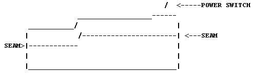
NOTE: The
rear vent holes are electrically connected to each other
so the RFI can not pass through them. -diskette or disk errors/hangs, loading/reading. Indicates an RFI problem with the P70's that caused intermittent drive failures during reading and writing. The fix was to insulate part of the power supply with 1/2" wide copper tape [typo, ONE inch] to prevent RFI leakage. There were two separate pieces of copper tape- one the full length of front horizontal seam, the second about 1" long on the seam from the corner of the ventilated end over to the long piece. There is a quick way to check to see
if you need this ECA, if you are familiar with opening
up your machine. Open up the back of the machine and
check the bus interface card, P/N 65x1567, for a 1000Mf
capacitor installed on the bottom of the card. If you
have this capacitor then you don't need ECA068. The
capacitor apparently helps eliminate data transfer noise
that can prevent the loading of multitasking operating
systems. 3M 1245 Embossed Shielding Tape Data Sheet This is what the doctor ordered and why the preacher danced. IBM used this. 1245 Tape came in widths from 1/4” to 23”, but 1" or a bit wider will do. Gleaming, Seductive Copper Foil 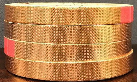 "1245 Tape consists of an embossed 1-ounce deadsoft copper foil backing and an aggressive pressure-sensitive acrylic adhesive. The edges of the embossed pattern pressed into the foil cut through the adhesive layer to establish reliable metal-to-metal contact between the backing and the application substrate." Technical Trivia on Copper
Tape To understand how a hair-thin slot can radiate more RF than a "swiss cheese" perforated panel, consider a half-wave dipole antenna (VHF TV antenna is a good example). It's a rod of metal surrounded by air, with the feed line connected in the middle. Now reverse the components and you have a "rod" of air surrounded by metal. Connect the feed wires to each side of the slot at the midpoint and there you are again - a half wave dipole. (The electromagnetic theory is actually a bit more involved than that, but it illustrates the concept). |
 #2 Use the latch on the side of the
square, white power plug to unfasten it. Disconnect the
small, black plug for the fan. Use diagonal cutters to
remove both the nylon wire ties holding the black tubing
on the plasma screen power plug. Work out the kinks and
pull the tubing towards the PSU. Squeeze the tabs on the
ends of the black power plug to unfasten it.
#2 Use the latch on the side of the
square, white power plug to unfasten it. Disconnect the
small, black plug for the fan. Use diagonal cutters to
remove both the nylon wire ties holding the black tubing
on the plasma screen power plug. Work out the kinks and
pull the tubing towards the PSU. Squeeze the tabs on the
ends of the black power plug to unfasten it.