8590/9590 PSUPossible Model 90 PSU Block Diagram 90 PSU Models API-0009 with Short Power Leads Pushbutton Power Switch Remove Model 90 PSU Open 90 PSU Myth of "Weak 90 PSU" Debunked! Testing the 90 PSU Planar Power Contact Oxidation Cleaning Your Contacts (for the PSU, not your eyes!) The power supply automatically switches to the 100-125 V ac range or to the 200-240 V ac range. The ac input is converted to dc outputs that supply the system with proper operating voltages. When the system is powered-off for 8 seconds or more and then powered-on, the power supply generates a 'power good' signal that resets system logic.
The presence of the 'power good' signal turns on
the green power-on light on the front of the system
indicating that the power supply is functioning
correctly. Model 90 PSU
Is Part of Case Structural Integrity
Possible Model 90 PSU Block Diagram 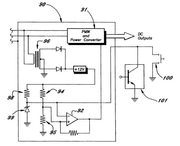
PWM Circuit 91 pulse width modulator control circuit [like Motorola SG1525A/1527A] Signal Generator Circuit 92 comparator 94, 95 voltage divider 96 small transformer 98 resistor 99 zener diode The comparator 92 receives from a first signal circuit a low voltage direct current reference signal established by a voltage divider 94, 95 supplied with rectified current transformed from the main supply voltage by a suitable small transformer 96. The comparator 92 also receives a controlled low voltage enable/disable signal varying between a first voltage and a second, higher voltage. The enable/disable signal is established by a regulated voltage divider formed by a resistor 98 and an associated Zener diode 99, to which is connected a current drain in the form of a switch device for grounding out the point of connection between the resistor and diode. The switch device, which functions at a low, logic level voltage (typically 5 volts) as distinguished from the voltage of the main supply (typically on the order of 100 volts or more), may be in the form of a manually operable switch 100 or a computer logic operable switch 101. In either instance, operation of the switch 100 or 101 functions for selecting between the first and second voltages for the enable/disable signal. Responding to the change in voltage of signals applied, the comparator 92 either delivers a signal forward to a shutdown or inhibit pin of the control circuit 91 or does not deliver a signal and thereby keeps the power on. The computer logic operable switch 101 may, for example, be associated with a telecommunications device for enabling remote control over the power on and power off states of the computer. Control 100 manually operable switch 101 computer logic operable switch 90 PSU Pinouts P1 and P2 Conductors 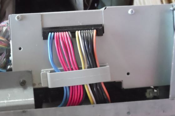 The 50 wire flat cable clamp is a TYCO / DEK 038-250 deklip / AEH 03-26-50 In reality, this cable clamp is NOT needed for keeping the power plugs on the edgecard, but are actually for SIMMplifying automated assembly. If you don't believe me, try pulling a seated power plug OFF a planar edge contact P1 is J26, P2 is J25 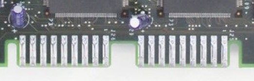 Check the voltages with connectors P1 and P2 plugged into the system board.
1 (P1) 2-7 (P1) + 4.8 + 5.25 1 (P1) 8,9 (P1) +11.5 +12.6 2 (P2) 1 (P2) -11.5 -12.6 B D + 4.8 + 5.25 B A +11.5 +12.6 P1 Conductor Functions (left to right) Blue +12v Red +5v Black Gnd P2 Conductor Functions (left to right) Yellow Power Good White On/Off Black Gnd Orange -12v
There are two systems fans: one in the
power supply, and a second fan on the base. If the power
supply fan does not work, replace the power supply. If
the second fan does not work, replace it. Power Supply Models There are at least two different PS for the 90- I have heard rumors of a 150W PS. Rich Wolos said You could start the old ones (yellow/black
short leads and plugs) by grounding the white wire to
the CASE. 64F4114 194 watts
(from Jan 92 HMM) 92F0088 215 watts
(from 96 HMM) API-0009 with Short Power Leads I foundt this image on OSTA.EE HERE 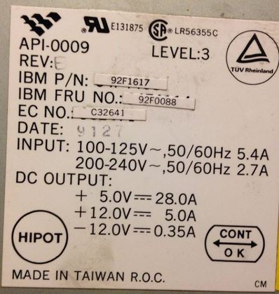 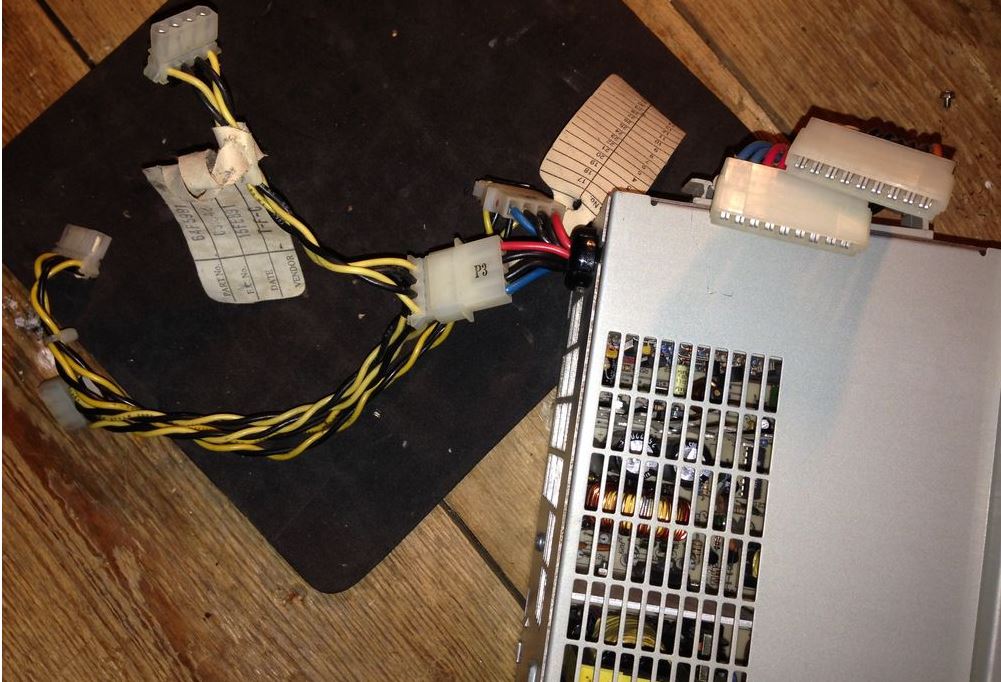 I read about this in some old ECAs, someone was asleep at the switch and the manufacturer cranked out a number of PSUs with very short leads. Nothing wrong with them otherwise. Rich Wolos referred to old PSU models with yellow/black wires, maybe he was confused over the HD cables plugged into the blue/red leads? Or are there old PSUs with short yellow/black power cables? The on/off switch is electrical. It is located at the
front left of the system and is a push-lock /
push-release type of switch. When the system is turned
on, the switch will be indented by 4 mm to show that
power is on. The flip switch was replaced with a push button to allow disabled users to simply push the switch, rather than requiring a "flipping" action. Remove Model 90 PSU  Unscrew captive screw on Power Supply Bracket (1). Pull top up and forward, away from PSU and continue rotating it forward until Bracket is free of bottom clips on the PSU. Now pull Bracket towards the rear of the system until the front tip can be pulled from drive shelf. Unscrew both black slotted hex washer screws (2) from the back of the system. NOTE: If you use a small bladed screwdriver, it may pop out of the slot on the 3/16 hex head / slotted screw. This can displace some metal to the outer side of the screw head which will keep a nutdriver from slipping all the way over the screw head... So... either always use a 3/16 nutdriver or a 3/16 wide screwdriver to prevent popping out of the slot.... Unscrew the single black slotted hex washer screw from the front case support bracket. Unplug the planar power supply sockets from the board and pull the PSU straight upward, so as to unhook the tabs at the back of the PSU from the rear wall of the case. PSU Side, Towards Complex 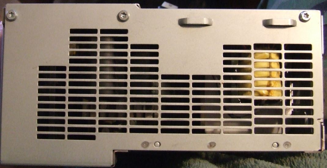 You need a T-15 security TORX. There are three Button Head Torx Security Cap Screws on the inner side (towards the complex). PSU Side, Planar Power Cables 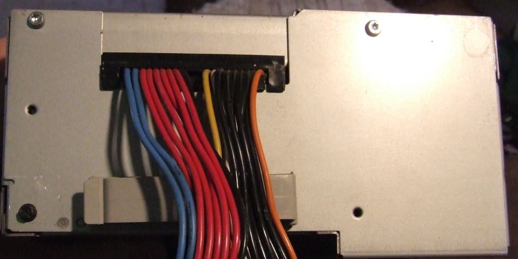 Two T15 are on the top edge on the outer side (towards the case). The black front PSU support screw is in the bottom left corner. NOTE: The black screw to the lower left corner also fastens through the front PSU support bracket and into the PSU case. In short, the cover will not come off with the black screw installed. PSU Front, Heatsink 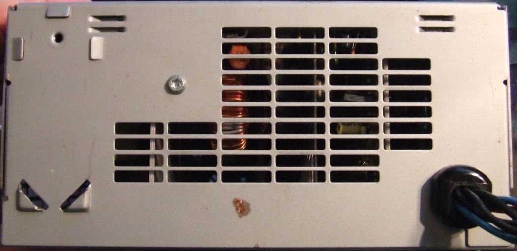 The one long T15 screw (towards the floppy) screws into a heatsink inside the PSU. Unclip Planar Power Cables. Flip PSU upside-down. Pull the case (bottom) straight
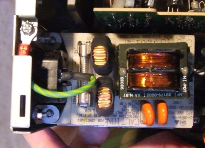
up. Remove PSU Fan The PSU quality is similar to a 8595 PSU.
The heatsinks are thinner than on a Model 95 (about
1/16ths to 3/16ths), but for a 215W PSU they are quite
acceptable. Model 90 PSU Fan Identity size Power Air
flow Air pressure
Noise Model About 1.15 m3/h Open frame, there is no enclosure around the mounting
screws... I was unable to determine the AWG as both wires are in
solid tubing.. Slightly bigger than the base fan's
24AWG, maybe 22AWG? Model 90 PSU Fan Power
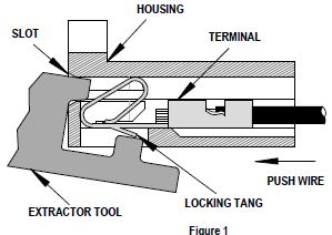
Connector Original P/N on terminal housing is 5051.
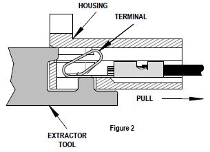
Engineering/Old PN: 5051-02 Part Number: 0022011022 2.50mm Pitch KK Wire-to-Board Housing, Female, Friction Lock, for 2759/5159 Crimp Terminals, 2 Circuits Extractor Tool (HT-2759) Removal of all 2.54mm (.100 in.) “KK” Terminals 1. Push the terminal forward in the housing so that the
locking tang is clearly visible.
NOTE: Or you could
use a jeweler's screwdriver -OR- a bobby pin to push the
locking tang up. If I was doing LOTS of terminal
replacement, I might buy his tool. For one or two, let
me dig through my toolbox or kitchen drawer.... This information is presented here, just in case I need
it in replacing the stock fans with some Noctua
models... Model 90 PSU Fuse Wickmann 19343
Datasheet or 03136.25
- 313 Series 3AB/3AG (6.3x32mm), Slo-Blo Fuse HMM Typo! "3 Amp
Fuse 72X8561" is dead wrong. Obey the machine! Little Big 90 > I'm worried about heat during extended sessions. There are no drives in the case sucking power and no bulky SCSI cable, but that still doesn't resolve the fact that the 90 really wasn't meant to take a Pentium. From Al Savage The SETI clients make sure that processor
utilization is always at 100%, so the CPUs are running
as hot as they can ever will. The P60 & P66
run a lot hotter than the P75/P90/P100 etc (13 watts,
IIRC), and I can put my hand on the heat sink and not
get burned. Hell, my AMDs run hotter. No baffle,
the front case fan moves about twice the air that any of
the clone cases do. The CPU's heat sink is
still directly in the airflow. I *do* keep the case vacuumed out,
though. I take the covers off every six
months and Kirby the guts. Dust builds up rapidly,
and is an excellent insulator. Both units are on a
3.1VA (BIG!) UPS. My opinion is that cooling is not a
problem on the 8590. I have not had to replace the
PS. I keep a "spare", preconfigured identical 8590 as
backup (just swap in HDD & go), but I've never used
it. Ed.
With either a 194 or 215W PSU, the 90 compares favorably
with the 9577 PSU, which was 194W. But nobody complains
about the "weak" 9577 PSU, do they? Testing the 90 PSU Peter Wendt sez: The most important point is that the "testing the power-supply" topic extends only on testing the thing as "one box" and *not* open it. You should leave that to trained experts, because it bears some risks - from which sudden death is the most evil (can spoil the whole day - and more). This sort of "shocking experience" should be left out. The easiest way to test the power-supply if it is still working at all is to open the case, look at the right side under the power-supply, locate the 2 plugs from the power supply to the planar and carefully unplug them by simply pulling them out. It might be a bit difficult to get them back this way - but if the power-supply is broken you will have to remove it anyways when you get another one, so we can leave that at the moment. Now: once you got the two plugs pulled out - look at them. The one "P1" marked connector has 2 blue, 6 red and 1 black cables ... that's the lesser important one at that point. The second "P2" marked is the one we need to look at closer. Do the following: re-attach the machine to the AC, then use a piece of wire or a bent paperclip and connect the white wire with one of the neighboring black ones. No danger - the highest voltage on that side of the power-supply is +12VDC. the white line is "+5V sense voltage" and the black one is GND. As long as the white wire isn't attached to GND the other voltages are 0 VDC (power supply de-activated) so there is no risk of accidentally shorting any voltage at all. In case the connection is good and the power-supply itself is functional the power-supply fan should come up - and most likely the machines' harddisks as well, which are directly attached to the power-supply with 4-wire DC-cables. If the power-supply comes up the problem sits somewhere else: - broken connection between ON/OFF switch and board (low - voltage) - broken planar - defective complex (but at least the green power-LED should light up then) In case nothing happens apart from a faint "click" inside the power-supply ... now ... get familiar with the idea of getting a spare from somewhere. It often pays trying to get an entire working machine rather than only a power-supply. Mod. 8590 without harddisks and memory often sold for some 30 - 40 bucks ... some ask 40$ for the power-supply alone. The 9590s may cost some more - the power-supplies however are identical as far as I know. The main difference between an 8590 and a 9590 is the 1.44MB FDD on the 8590 and that some versions come with only a 512K XGA-1 on the planar. Everything else (processor board, memory, power-supply, harddisks) can be interchanged among the models. A high pitch whistle indicates the PSU will not pass this test and is broken. Usually these power-supplies are pretty reliable - some of them suffer on "long term problems" with dust contamination and related overheating. In case there were an over-current condition (overload on +5V / +12V lines) it should come up in the above-mentioned test - if that malfunction is not caused by the harddisks. Try detaching the 4-pin power-plugs from the harddisk(s) and retry ... if the malfunction persists even with nothing attached to the power-supply it is definitely broken. To fix these kind of "switching power supplies" you need some more equipment than only a multimeter, a pair of scissors and a roll of duct-tape. Parts inside these supplied are directly connected to mains AC and converted into DC impulses of hazardous voltages and frequencies ... so I would not even recommend trying to open the box if you do not exactly know what you are doing. In case of doubt: leave it as it is. There are a few "power-supply gurus" out which may be able to repair the unit - but they are hard to find. Planar Power Supply Contacts
Forget Says: Well, strange problem here. My venerable PS/2 9590 appears to have gone down, but with a strange problem. Has anyone ever seen this: Basically I plug it in and turn it on--get nothing, not a peep. Eventually, maybe in about 10 minutes, the power supply turn on, disks spin, etc and system displays a 0002102B, then goes completely dead again. I can't Ctrl-Alt-Del or even get the keyboard to flip on and off the Numlock / Capslock keys. New power supply, same thing. New processor complex, same thing (except no 0002102B, just nothing). Yank out all memory except 2 known good SIMMs in right spots, same thing Yank out all MCA cards and disconnect drives, same thing. Replace battery, same thing If I "short out" the power supply, and I have two of them, the fan spins up just like it should. So, I'm thinking bad planar board? It about the only thing that I haven't replaced. Seems strange it would be that however since all the real smarts are on the processor complex, and displaying an error means the complex kinda/sorta works, I think. Anyway, anyone have any advice? I think this would actually be my 1st PS/2 to die of natural causes, not counting things like disk drives and power supplies. Later: Still dead. I think I got rid of the 0002102B through a combination of paring down the memory and removing/inserting cards. I blew everything out with compressed air and still have essentially the same issue. It turn on appears to "run" as I do get the cursor in the upper left and memory starts counting and sometimes finishes, but eventually the system just stops dead. I'm beginning to think I just have two power supplies that have the same symptom. After the system dies, the only way to revive it is to unplug the power supply for about an hour and try again. Turning on/off the switch does nothing. Wolfgang Gehl Nails It The planar power connector seems to be the problem. Keep in mind: "The 90 (Little Big 90) uses a card edge connector on the planar that the PSU plug fits over. Check the planar connector for oxidation or weirdness of the solder pad contacts." Carefully clean the planar's card edge power connector. For whatever reason it tends to oxidize heavily. I've been there and it works for me. Regards, Wolfgang Cleaning Planar and Plugs
(1) Remove the power supply from the case. Look HERE. First, remove the power connections from any internal devices (hard drives, CD-ROMs, etc), remove the sheet metal "bracket" between the power supply and the drive cage, then remove the screws in the back. "Flop" the power supply 180 degrees from left to right to make it easier to access the planar power connectors, and then remove the connectors. (2) At this point, you can easily look at the planar and power supply connections, and they'll probably look OK. Don't be fooled. Take a small piece of ScotchBrite (that green plastic scrubby stuff that is frequently used to scrub pots and pans) and LIGHTLY buff the planar solder pads to make them nice and shiny. Buff the power supply connector fingers with an emery board - again, just a light touch is needed, rub each finger two or three times. (3) Slide the power supply connectors on the motherboard pads, then remove the power supply connectors again. Do each of the pads show marks where the power supply connector fingers dug into the solder pads? If not, you need to re-tension the fingers that did not make a mark. (4) Once all the fingers make marks, re-install the power supply and power connections to your devices. Power up and enjoy reliable 9590 power for several more years. |
||||||||||||||||||||||||||||||||||||||||||||||||||||||||||||||