85, 95, and 3511 PSExpect utter Kaos!
Moving PSU to Access Memory, Battery, or Devices Power Supply Revisions Max Amp and Power Draw 400W PSU Dimensions 71G4602 Thoughts on Shipping Cracked T1 on Horizontal PCB T1 Transformer Model Checking Power Supply Voltages Quick Op Panel Check Primary Power Supply Voltages Drive Connector Voltages Reliability High Quality Side Cover Fan Side Cover Fan Orientation Case Airflow Side Cover Fan Construction Side Cover Fan Revisions Cover Fan Cable Assembly Side Cover Fan Troubleshooting How Does The Fan Look Installed? (Takes you to Jim Shorney's site) Deriving 17vdc from the Power Connector Trying to Plug PSU Onto Planar Plug when case is Horizontal E-Clip for PS Knob Assembly Air Deflector on 95A PSU Opening the 400 Watt PSU Security Torx Security Phillips Remove Screws in Rear Wall Removing AMP Planar Power Socket Retainer PSU Rear Wall Catches Remove Inner Wall from Case Slots Thoughts on Factory PSU Assembly PCB Guides Horizontal PCB Guides 95A Power Supply Exposed! Power Supply AC Socket Fan PSU Fan Connector Fan Cushion Fan Control PCB 2 Pin Fan Connector Fuse Blown Transformer Moving the Power Supply to Access Memory, Battery, or Devices Components like the CR2023 battery, planar memory, and devices (cabling!) on the IBM Model 95 system are either behind the PSU or require you to drop the PSU in order to get enough room to work on the device.. On the outer side of the power supply there is a spring-loaded power supply retaining knob. Rotate this about four times until it releases the power supply which you can then tilt out of the system. The power supply is not completely removed from the system unit. NOTE! Do not try to remove the blue knob! Once the knob pops loose from the threads, you don't need to rotate it any more. Warning! ------------------------------------------------~ When dropping the PSU, unplug the AC power cable from the PSU! NOTE! When dropping the PSU, consider unplugging any drive power plugs from the three sockets on the front of the PSU. NOTE! When swinging the PSU back up to reseat it, ensure drive power cables AND any SCSI cables are out of the way of the front lower edge of the PSU. Warning! When re-seating the PSU, after ensuring any cables are not trapped underneath the front edge, press the PSU onto the Planar PSU socket. Press the blue knob inward so it starts, then tighten it down with no more than finger pressure until firm. Applying excessive torque WILL pop the e-clip on the screw shaft. Where that little semicircle of steel then ends up is up to chance.Maybe in the PSU case... Maybe hanging on a planar component... If you are lucky, it will fall down to the bottom of the computer's case and not short anything... Power Supply Revisions 335Watt (FRU 92F0051 / PN 92F1596 / SMP-332AB) in all
8595 machines and later "small" Server 85 (those with
486SX and 8-bit planar SCSI). 400Watt (FRU 92F0267 / PN 71G4602 / SMP-400BP) was
introduced for the Server 95A. The 9595-xLx and -xMx
however use the 335W since they are souped up 8595 only.
The bigger PSU can be identified by the LED and
test-button at the top left corner, when looking at the
installed PSU. The "bigger" Server 85 (486DX2 and F/W
planar SCSI) have this one as well as the 3511 expansion
unit. Delta "SMP" NOTE! The dual
serial / dual parallel port planars for the 95A systems
and the 9585-X/K/N planars use PTC resistors to protect
the planar from excessive current. The single serial /
single parallel port planars for 95 systems lack these
devices. So yes, the 400W can be used in a 8595 or
9595,but watch your power draw. Personally, I can't see
how you could load a 95 up unless you use huge old
fashioned drives and a bunch of Type 5 cards....
Whatever. Just be careful out there... Maximum Current and Power Draw The system provides a separate power source for internal SCSI drives through three 4-pin connectors on the power supply (see Power Supply Connectors). The system board voltages are +5 V dc, +12 V dc, and -12 V dc. The drive voltages are +5 V dc and +12 V dc. The following are the maximum current and power considerations used in designing the power supply and system board. The formulas used to determine the power requirements and the voltage regulation tolerances for adapters are in the Micro Channel architecture information in the IBM Personal System/2 Hardware Interface Technical Reference--Architectures. Component Maximum
Current Note Some adapters
and drives draw more current than the recommended
limits. These adapters and drives can be installed in
the system; however, the power supply will shut down if
the total power used exceeds the maximum available
power. 400W PSU
Dimensions 71G4602 Thoughts
on Shipping Once inside a PSU, you should open it to chase
the bits out. Best to tape up all vents with newspaper
to keep the foam OUT. I personally stay away from blown foam as the
ONLY padding. It is rigid, and IMHO transmits shock to
the object inside. If the foamed object is then placed
in a larger box with foam peanuts or bubble pack or
captive air, then any shock is absorbed by the loose
packing. YMMV. For shipping a PSU by itself, I think a box with
4" of space around the PSU leaves enough room for
adequate bubble pack or captive air. Not a fan of a
foamed-in PSU in a box as the lone shipping container.
YMMV. In the end, we want to keep the ferrite transformer
cores happy, Blown
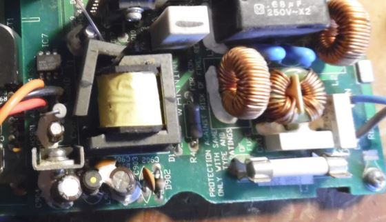
Transformer Cracked T1
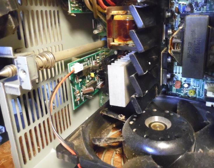
on Horizontal PCB :( Finally dug out another 400w from on the porch, and I
heard a light metallic tinkle when moving it. Not
knowing what, I took it up to the operating table
today... I do not see other damaged components, to me it looks
like a physical shock cracked this... T1
Transformer Model
Checking Power Supply Voltages PS/2 - Server 85, Model 95 and 3511 Some power supplies have a built-in test switch and LED on the side of the power supply (there is no need to check voltages). On those power supplies, disconnect the power supply from the system board, and remove all cables except the power cord. Power-on the power supply and push the test button. If the LED lights up, and the power supply fan runs, the power supply is OK. 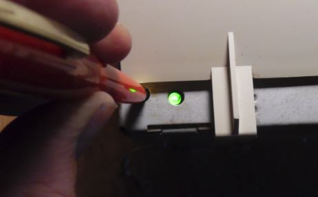 On all other power supplies, short pin 1 to pin 2 and read the voltages on the other pins. If the voltages are correct, and the power supply fan runs, the power supply is OK. NOTE: If you use a test button or short pins 1 and 2, the PSU will operate at a No-Load level, eg. the fan will be on low speed. This very PSU tested green with nothing attached, but when plugged into a system, the fan continuously searched high and low. UPDATE: This is the 400w PSU fan that was continuously searching... "But after I hooked a couple of hard disks on it, it was running fine for > 20'." Some repressed memories came up from the depths... If the PSU is under no-load, then the fan will be operating at an unknown low speed. PWM controllers spread out the pulses, so the slower the motor, the farther apart the pulses. Amplitude stays at 12v. So it is very possible the growly fan I heard during test was the fan controller "kicking" the fan over with widely spread pulses. This is interesting, as it illustrates the PSU fan control functions, which up to now have been ignored (as long as it works). An experiment would be to stick a 95A PSU on a Kill-A-Watt meter and an oscilloscope to watch the waveform. It would be more trouble than it's worth (except to be crowned "Alpha Geek") to determine at what load the fan control goes from Low to High. In closing, it is quite possible the PWM stuff needs to operate under load (how much, dunno) before it can settle down. Quickee Op Panel Check Pull Op Panel out front of system. Leave
PSU connected and plugged in. Short pins 3-6 OR 5-4 and system should power
up if the Op Panel board and cable are good. Nothing
will happen if you short 5-6 or 3-4.
Primary
Power
Supply Voltages AMP socket 213516-1 Receptacle, 21 Position, 43 Deg,
Metimate Datasheet
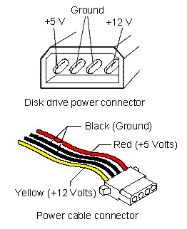 Wire Colors for Disk Drive Power Connector IBM used Yellow-Black-Black-Yellow. If the power supply shuts down, or appears to fail at
power-on, you might have one of the following
problems: Or the Remote Maintenance Service Jumper is not correct. But to answer your question:
the Mod. 95 PSU is not known for any particular failure.
There was a series of downlevel "Delta /US" made 400
Watt PSUs, which failed after a short time - but these
have blown themselves to hell already and none of them
has seen the year 1992.
The 95-PSU is rather complex inside. The main functions are distributed among a number of smaller boards and tracking down failures isn't easy - except you have blown and burned parts. In most cases however the failing components are not that obvious to find. The most common failure is the "no turning on" failure with the short clicking noise and the high-pitch whistle afterwards. I don't know which component causes this - and how to repair it. Malfunctions that the PSU works for some time and then -by no obvious reason- switches off (thermal problem) are only reported for *extremely* dirty PSUs, mainly accompanied by blocked fans. After some time running the internal protection circuit causes a "thermal shutdown" due to overheating. This could be fixed in most cases by cleaning the thing and replacing the fan. The commonly known problem with overheating and burning the stand-by part of the PSU are not reported for the 95 PSU ... it is no Magnetek / Italy made PSU ... :-) High
Quality A guy who (professionally) repairs
switched power supplies looked into a dead 95 PSU and
was surprised as well. "How old did you say are the
Mod. 95s ?" If you have an AC wattmeter - plug in
the PSU, shorten the "powerswitch pin" and test out
the idle wattage it takes. It is much lesser than the
average wattage taken from a 145W chop-suey PSU from
China or elsewhere. And the 95 PSU has 380 - 400W
output power .... Even the notorious Magnetek "Made in
Italy" power supplies for the 35/56/76 are pretty good
on their technical data and performance ... apart from
the unlucky tendency to fry themselves to an early
death. The concept was good - the manufacturer wasn't.
(Or the quality control). Side
Cover Fan
Part of the following was redone based on info found by Ross Barker (Ross pulled up anchor- he's on the high seas again) This is a swirling debate... For now, I'd like to point out the difference between the 95 and 95A plastic end bracket for the fan. The 95A bracket has a slot and a beefier catch. Airflow
Open to interpretation... The significant points- air
is pulled through the top grilles, sucked through the
adapter cards, down the side wall through the side wall
fan. Air is sucked over the top of the PSU,
past the complex, over the memory, then into the PSU
where it is blown out through the exhaust. Though
looking at a PSU shows the memory has a blank surface in
front of it, probably to force airflow past it. NOTE: The PSU for
the 3511 Enclosure has the louvers on the lower, inner
edge taped off. These louvers ventilate the SIMMs on the
95 planar. YMMV, I need to source this factoid... Side Fan Construction Unlike to "real motors" the resistance
does not change when you turn the fan ... normal
DC-motors act as generators once driven. This thing
doesn't. However: 137 Ohms would give a current of
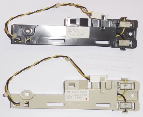
about 125 mA - still below the specs. Side Fan Revisions 64F4470, EC C31557, mfd. 042391 137 ohms 64F4470, EC C32546, mfd. 121391 1.31K Ohm Hosiden HMK 3404-01-092, DC 17v. 0.185A 64F4470, EC C32546, mfd. 031892 1.32K Ohm 95A Side cooling fan fan Possibly this means any fan made on or after 121391
will be a 1.3K ohm model. HMM says 61G3824, the older style is P/N 84F9284, the
newer style is P/N 60G9828. For purposes of clarity, I
wedged the white planar connector into the top. 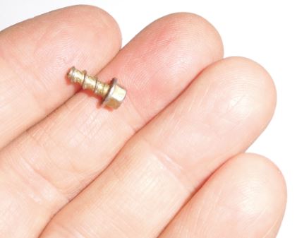
Side Fan Troubleshooting If the access cover fan does not work, check: Check the spring contacts on the fan bracket to see that they stick out far enough. Over time, with repeated removal and installation of the side cover, the contacts will be pushed back into their guides. Carefully pull them out again. Make sure the free end of the spring enters the recess when not under pressure (that way it's lined up when you are using BOTH hands to install the side cover...) Power to fan: 17 V dc (+/- 1.4 V dc) at the two fan cable pins on the base. If voltage is correct, check for 1.3K ohms (+/- 10%) between fan terminals (Ed. I have an older fan that has 137 ohms. Runs fine.) If resistance is incorrect, replace the fan. If resistance is correct, check spring clip connectors. (If good, there isn't a fan problem). If voltage is incorrect, unplug fan cable from connector J28 on planar and check cable assembly for continuity. If cable has continuity, replace the system board. If the cable does not have continuity, replace it. Deriving
17vdc from the power connector Just trot down to Best Buy and pick up the dual serial/parallel planar for $49.99 and pop it in? Or will you whip out your trusty 25W soldering iron and take charge of your own destiny? If you are of the adventurous type, read on! >So if J28 does not have 17vdc present, can you come
off pin 9 and pin 4? >That was my intent- how to derive an alternate
source of 17vdc from the planar power socket... Alternatively: pin 7 of the PSU-connector
deliveres -12V, pin 3 +5V ... both add to +17V as well.
Only need to watch the polarity. (Ed. Verify the polarity
with a voltmeter/DMM. Do not assume anything with a 9595
dual serial/parallel planar. One bzzt! and you may burn
something else on the planar. The Power Supply will be
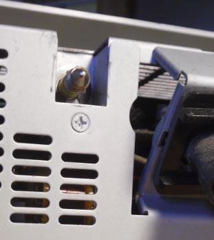
fine though...) Trying to Plug PSU Onto Planar Plug when case is Horizontal SuperVinx said: Someone gave me an 9585-ONG, formerly owned by a bank. The PSU was easy to remove, but it was hard to reseat the power connectors between the PSU and the planar while the system was horizontal. I've found that the 9585 must be in the vertical position, all the way to the right on the mounting pins, in order to seat with minimal effort. E-Clip How were all these PSUs missing E-Clips on the PSU knob? How it happens- (from Charles)
If you crank on it hard enough, you WILL deform the clip, dislodging it from the shaft, USUALLY the next time the PSU is unseated. It starts with a very hard counterclockwise turn, and then you notice that that nothing is moving as you turn the knob. Then when you pull -- pop! The e-clip finally gives way. Charles Lasitter My nuts 'n bolts reply
The thread outer diameter is roughly .310". So
the outside shaft diameter will probably be a little
larger, maybe .318 (standard fractional dimension,
IIRC) The diameter of the part where the eclip rides should be .208 plus/minus maybe .003". Thickness of the e-clip is .025". Bob Watts From the god Emperor of Microchannel On a lark, I went to Ace Hardware. Ambled
over to the fastener center. Whipped open the Hillman
External Retaining Rings box. Pulled out a 5/16th
Retaining Ring, 08236-00379 for a whopping 20 cents
each. They aren't as loose as the IBM e-clip, but you can turn then with your fingers (the NAPA ones wouldn't) 95 PS vs 95A PS 95A Air Deflector 
It starts on the left front corner of the PSU. 17.2cm/6 13/16ths" wide. The air baffle extends towards the complex 8.7cm/3 1/4" inch from the outer edge of the PSU. The air baffle has a maximum height of 3cm/1.5". Although this air deflector was available as a separate part, the ones I have are fastened with adhesive to the PSU case, and the outer side of the PSU case is tack welded to the front and back faces. So you need to diddle around and take off the inner PSU side. 95A PS Delta model SMP-400BP? I opened up my 95A 400W power supply. I do NOT advise anyone to attempt to fix or modify the power supply. I take NO responsibility for what you do! You are doing this on your own! This page is ONLY to expose you to the quality construction used on the 85/95 series systems! I have left many details out, because I'd rather not have people opening these power supplies. They have pretty big capacitors in there. Seen bigger, but these will hold a sufficient charge to ruin your day. For entertainment only! In no way do I suggest that you try this! I don't have safety tips for the proper de-energizing of the circuitry for power supplies that have been used recently. I used a power supply that hadn't been powered up for over six months. Assume all heatsinks are live
if this power supply was plugged in! Opening the 400 Watt PSU (others similar) Here are the tools and procedures for a (relatively) painless way to open a PSU to clean it. I do not have any schematics for this or any other PS/2. Everything here is either scoured from the internet or a result of (usually painful) personal experience. Security Torx Menards had the Truecraft model #6232 32 Piece Bit & Socket Magnetic Ratcheting Driver Sets (about $20). It has tamper proof T10-T40 Torx bits. The bits and case are Taiwanese (I'll buy from OUR china any day!) and the ratchet and sockets are US. The bits are heat treated S2 steel (good stuff). You will need the security T-15 bit. Craftsman has a set of security bits and magnetic handle for @ $27, BUT it has the security Pillips, Torx, spanner, and others. Nice and compact. Security Phillips I made my "security phillips" screwdriver with a cheap old phillips. Threw it into a vise and hacksawed two slots at right angles to the edges. It has four separate points sticking up around the center now. I would get a real security phillips if I was doing this a lot. It worked but I would not want to really torque on it. Removing
the PS Knob Shaft
(only needed for total PSU
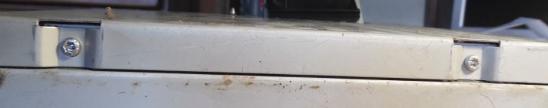
teardown) To remove the PSU rear wall, you need to remove the TP2
Phillips just below the PSU fastening screw. You can
leave the top TP2 alone, and leave the PSU Knob right
where it is. It does not pass through any PCBs. Remove Bottom Inner Edge Screws Place PSU on it's outer side. Whip out your T15
Security Torx and remove both screws. Removing the Planar Power Socket
See the hooks holding on the bottom of
the socket? While pulling up on the collar, pry the
hooks away from the socket, one end on one side,
then the other end. Move to the other side and work off
the hooks again one at a time. 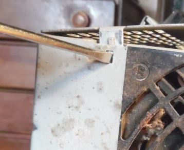 Remove Inner Wall from Case Slots Once all screws and the planar power connector are removed, and the Inner Wall is freed from the rear PSU case wall, then turn your attention to the top inner edge. There are three tabs from the top of the inner PSU case wall that slot into the top PSU case wall. I ended up flexing the inner wall up and down while pulling out and up at roughly 45 degrees. Images to come when I open one of my last, extra 400w PSUs. Thoughts on Factory PSU Assembly Looking at the shell, it seems that the air deflector was put on last. The front wall has tabs that fit onto slots in the top wall of the PSU. Like the back wall, but in front... The air deflector has two alignment tabs that extend over the front wall of the case, but those tabs are not connected with adhesive. My guess - air deflector was applied to finished PSUs, and any adhesive is under "lean-to". For visualization of the case, the front, top, and rear walls are an inverted "U". The inner wall is a separate piece. The front wall and the bottom wall form an "L". From my perils of pulling this 400 apart, if you wandt to fully disassemble one, you need to remove the two air deflector "tabs" that hang over the front wall of the PSU. 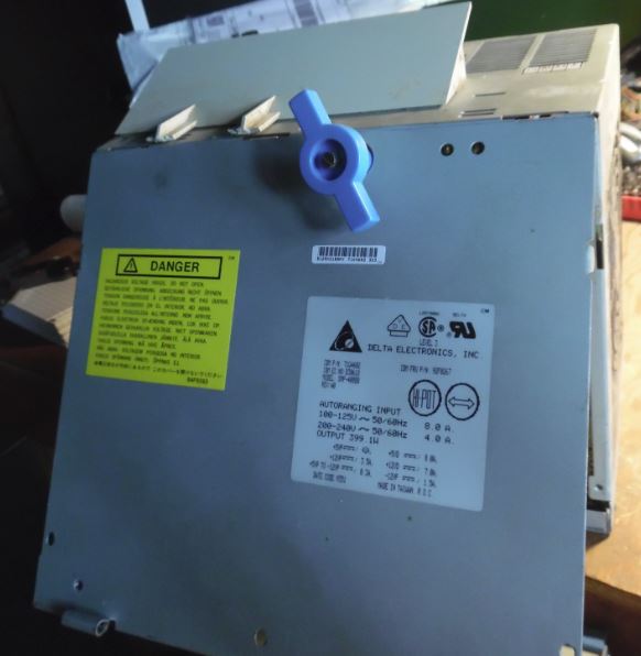 Disassembled Well Parts 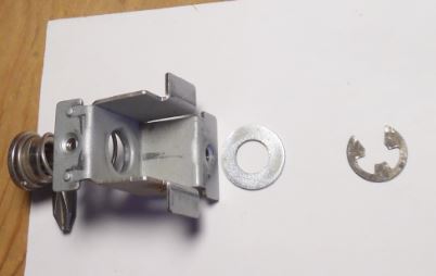 PCB Guides  This is the inverted "U", front, top, and rear wall of the PSU. Note the PCB guides along the outer edge of the PSU. Notice the metal clip at each lower end of the "U" (case upside down, clips at upper ends of "U"). These clips hold the horizontal PCB's bracket. The way this is laid out, it appears the inverted "U" slides down over the vertical PCB. Note the PCB guides for the horizontal PCB. The single double guide at the middle of each end (front and rear) allows the horizontal PCB to be pushed over the double guide and slide forward to engage the case clips. Vertical and Horizontal PCB Bracket 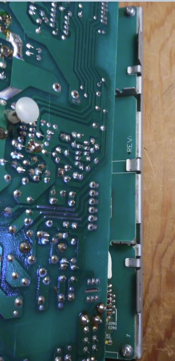 This shows the vertical PCB bracket cut-outs, and how the clips fit over the vertical PCB. Also see the "U"s where the horizontal PCB slides in. Vertical PCB Bracket Clips 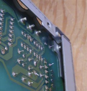 The bracket on the vertical PCB hooks under the clips at the front and rear of the "U". Note the threaded hole for one of the two T15 Torx screws holding the front wall on. Vertical PCB Bracket Screw 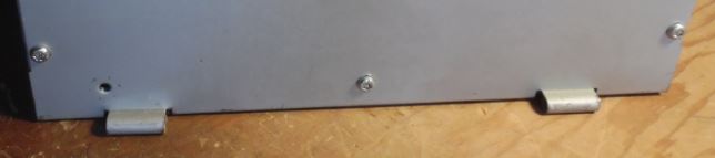 The vertical PCB Bracket is fastened dead center with a T15 Torx. Horizontal PCB Guides 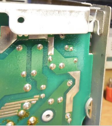 See the way that the corner of the bracket is secured by the clips at the corner? Also, note the double guide near the bottom right of the picture. There is a semi-circular cut-out that the PCB clears when being assembled, and once the PCB reaches the single PCB guides, the horizontal PCB is pushed to the outside wall, and the corner clips and the center double PCB guide are engaged. Oh
My God! 95A Power Supply Exposed! 95A
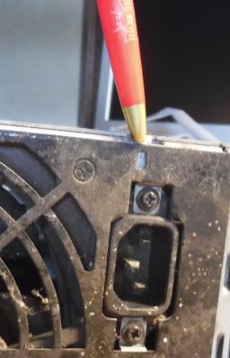
Power Supply AC Socket Delta 10GEEW3E, 10A 115/230 volts. Mfr 9337 by Delta. Datasheet Fan
Burnout protection function at
locked rotor condition Reverse polarity protection
function NOTE: Both the 329w
and 400w fans do NOT have sensors, and the fan does
NOT have PWM circuitry inside it. 329w 12v 0.45A 5.4W 2,800 RPM 2.5 m3/min (88.2 CFM) 53.9 Pa 40 dB 109P1212H402 page
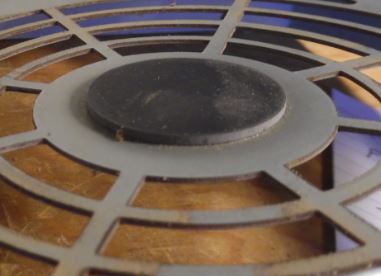
Datasheet Model 109P1212H1021 DC12V 0.52A - 6.24W Seven "rounded" blades, ribless, uses metal clips for mounting screws 109P - Plastics 109R1212H102(1021) Datasheet Fan with sticker removed 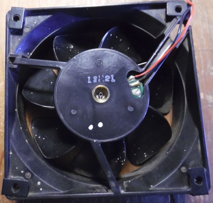 Once you carefully peel off the round black sticker from the back of the fan, you will see it has three contacts (only 12v and GND used) and the lone identifier, "12H21". See the small fan spindle in the well. A SMALL e-clip holds the fan in the hub. Sanyo Denki Co. DC San Ace Brushless After cracking open the oyster,
you might be able to oil the bearing with the fan in
the case. I finally noticed this while
re-assembling my sick 400 watt PSU. The fan hub is
pulled onto this when the mounting screws are
tightened. Vibration control? Fan Control PCB This Fan Control might monitor
both fan voltage drop and PSU output voltage drop. Think about it, you can't just
monitor fan speed without monitoring PSU load.
Monitoring current vice voltage drop takes higher
rated components because current measuring device must
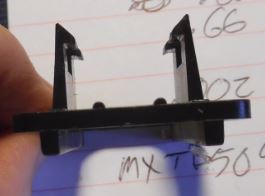
be in series and must be able to handle amperage. Molex 5051 Series Headers & Wire Housings - hooray! 2 Pin white connector marked: 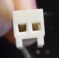 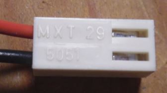 MXT 29 5051 For the fan wires: 2.50mm Pitch KK® Wire-to-Board Housing, Female, Friction Lock, for 2759/5159 Crimp Terminals, 2 Circuits Part Number: 22-01-1022 Engineering/Old PN:5051-02 2 Pin Header on Fan Control PCB 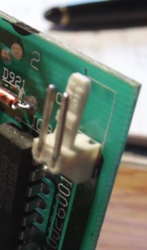 Connector is marked: MXT B (or "8", cramped space) 5046 For the Fan control PCB header Mini-Latch™ Wire-to-Board Header, Right Angle, Friction Lock, 2 Circuits, Tin (Sn) Plating Part Number: 22-05-1022 Engineering/Old PN:5046-02A Pins look to be .66mm / .0025" KK® Cat Ear Crimp Terminal 5159, 22-28 AWG Engineering/Old PN: 5159 Phosphor Bronze, Tin (Sn) Plating or Brass, Tin (Sn) over Copper Plating 24AWG, Type TR-64 AWM VW-1 1007 E44013, wires say "DENKO" and "DAIICHI" Dai-Ichi made the small gauge wires for DC fan manufacturers. PSU Fuse
T8AH 250V. If this
fuse blows, remove the short circuit from the output.
Though if this has blown, something is wrong because
the power supply should have shut down by itself!!! If
the fuse blows again after removing a shorted output,
I recommend you take a power supply to a real
electronics repair tech. 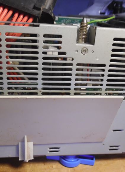 After fastening top of well to the top side of the PSU, pass the PSU Knob Shaft through the hole in the well. Now put the PSU on it's side. This makes applying compression to the PSU Knob easy. Installing E-clip 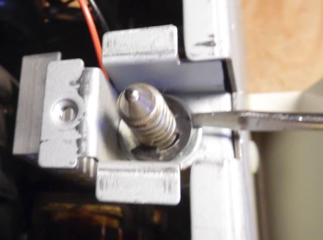 With the PSU resting on the blue knob, it is much simpler to keep the shaft at the proper protrusion. Place the e-clip so the outer ends fit into the groove and use a standard screwdriver to push the clip onto the shaft. Inserting Rear Wall 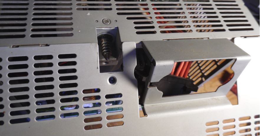 The rear wall tabs fit into the slots in the top wall. Blown Transformer Unfortunate victim is Frans Huizing One day, smoke came from the PSU and it promptly shut itself down. I opened it up, (yes, I have the proper tool) and found 3 pieces of ferrite loose in the supply: part of the core of a transformer. One piece had lodged itself between what looks like a small regulator board and the main circuit board where the short caused some physical damage to an area that is not used. Yes, the 8A fuse was blown. However, on the little circuit board on the right top corner are , what looks like, 3 resistors. The middle one has been fatally damaged. Now I come to my questions: Where can I find the schematic for this supply.(Delta, SMP-400BB, EC3 D30618) And can you think of any reason other than a manufacturing flaw why that xformer fell apart? Dr Jim Shorney replies Jim sez >Why the hell would a core fail like this? Powered ferrite cores aren't a
terribly mechanically robust thing. Could have been
dropped. Or it could have been cracked by an
intense high-frequency spike from a nearby (or direct)
lightning strike. |
 Thanks to Rick Starich for getting me to
do this!
Thanks to Rick Starich for getting me to
do this!