|
Pinout for 95A Op Panel Multimedia Port Pinout Pinout for Op Panel Connector Op Panel Presence Detect Codes Register Information LED Module HDLG-2416 Information Cheap Op Panel Lens Redo Thoughts on Adding a HD LED Peter's Two-Color LED Works on early non-shuttered switch only. Shorney's Shortcut Origin of Op Panel Board Button Sizes Power Switch Shutter Testing Power Switch Replacement Power Switch Odd LED Behavior LED Panel Driver Programs Schematic of Audio Stage
General Description System board provides a 2-by-17-pin Berg connector to the operator panel. The operator panel consists of the ON/OFF switch, a speaker, a fixed-disk access light, a power-good light, and an information panel. It displays eight characters using 5-by-7 dot LED displays. The information panel is accessed through an 8-bit data bus, which is controlled through a set of I/O ports 95A Op Panel Multimedia Pinout
Operator
Panel Registers HDLG-2416LED
Display (pdf data
sheet) Thanks to Jelte Roelfsema Now this is where I went to work. Imagine
what if you took the codes that are output to the
parallel port and hooked them into the HDLG-2416? We
would need a hex to ASCII converter to feed the HDLG,
but with the capabilities and features afforded by the
2416, why not take the time? Cheap Op Panel Lens Redo From Tony Ingenoso Tired of the scuffed up scratched LED display panel on your M95? Would you like it to look as if it were new again? Here's how -- it takes about 1 minute and makes all the difference in the world from an esthetic point of view. 1) Remove the bezel containing the LED panel cover. Thoughts on Adding a HD LED >I am thinking of using 2 colored LED, and replace the power on LED. From Peter From Jim Shorney It should certianly be possible to wire in a simple switching circuit with an NPN transistor on the HD LED to take care of the difference and allow use of a common-anode bicolor LED, providing the +5 can source a few extra milliamps. I haven't figured out (yet) if this comes from hard power or is a signal output from the PS/planar. The other possibility is to use a common-cathode LED and share the resistor for the power LED, but I'm not sure how well this would work. LED's are diodes, after all, so the two sources would be isolated from each other (in theory), but I'm not sure what this would do to the brightness of the LED's. I may play around with these ideas in the future, but I wanted to keep the initial mod as simple as possible for those who might be comfortable with a soldering iron but don't possess sufficient knowledge to handle wiring up transistors and such. From Peter *But* the visibility is still bad.
What you need were a "NAND" function that switches off
the green power LED when the red HD LED comes on ...
that would make the color either green *or* red but not
a diffuse orange when both come on. From Peter >An LED behind the display window seems
to be the best overall solution. >I think I would go with green,
myself. And I'm still thinking about replaceing
the power LED with a blue one... Peter's Two Color HD LED Peter's minimalistic "Two-Color LED" Solution
+-----+-------o
HD (Pin 4) ------------------------------------------------------------
*
Principle of Operation * The two LED-parts use
the existing 330 Ohms resistor in common. The PNP
transistor gets minus-potential over the 47K
resistor and the green LED lights up. Even when the
HD-pin does not feed minus to the resistor (tri-states)
the GND connection is given over the red LED part and
the current-limiting resistor, so that the green LED
will light under any circumstance. Once the HD-pin gets
positive (on HD operation) the positive +5V pulse will
turn Base of the transistor positive and the green LED
goes blank - the red LED is then on and indicates HD
activity. The type of the PNP-transistor is
uncritical. Any type will do. I used this 2SA608 while I
had it ... In case you want to return to original
condition you only need to remove the circuitry and
resolder the single green LED. Pretty easy, eh ? I found out that my original concept works only with
*one* panel card, which sits in a very early Mod.
8595-AH9 (without shutter). All my machines have the
same panel card that Jim described and to which he
published a "revised version" of my PNP-transistor
solution. The two cards only differ through the position
of the current-limiting resistor for the "power LED" -
but that makes a bit difference. Sigh. Shorney's Shortcut Parts required: An LED of the size, shape, and color desired One .25 Watt, 330 Ohm resistor Two short lengths of small-gauge hookup wire Some small heat-shrink tubing An IBM Model 95 Tools required: Instructions: 1. Trim the leads of the resistor and the anode lead (the long leg) of the LED short, and solder one lead of the resistor to the anode of the LED. 2. Solder the two lengths of hookup wire to the other resistor lead and the cathode (short leg) of the LED. 3. Cover the soldered connections with the heat-shrink tubing and, well, "heat shrink" it. 4. Pull your 95 apart, and unplug and remove the operator panel display PCB (you do know how to do this, right?). 5. Secure the LED in your desired mounting location (more on this in a bit) and cut and strip the two free wire ends to length; the anode lead (the one coming from the resistor) will be soldered to pin 4 of the ribbon cable connector, and the cathode lead will be soldered to the frontmost of the two speaker connector pins (ground). Make your connections on the bottom of the PCB. 6. That's it! Install the PCB back in your model 95, taking care not to snag your wires as you slide the PCB back in. Enjoy your hard disk light! Now, as to mounting location for the
LED... Being into vintage ham radio gear, I subscribe to
the "drill no holes" school of mods. Finding a
suitable location for the LED, without altering or
detracting from the aesthetics of the machine, is the
hardest part of this adventure. While I'm at it, I may just replace the power LED with one of these blue LED's that I have around here. Seems apropriate... This info will appear on my web site. Someday. Subject: Peter's LED circuit I finally got around to trying Peter's
nifty circuit for a two-color HDD LED in a model
95. In the process, I discovered that there are at
least two variations of the info panel PCB. Mine
differs from Peter's in the location of the LED
resistor, so I had to change the circuit as shown
below: That having been said, I also tried a
rectangular red LED behind the display panel on another
95. I must say, I like the way it looks. I
fixed it with hot glue to the bottom of the rightmost
operator display LED so it appears directly below the
rightmost character of the display. Now I need to
decide which way I like better.... Origin of Op Panel Board >BTW. what is the switch 1 for on the control panel PCB ??? Peter replies: The IBM instructor told us, that the panel card has been taken from some 3270 control unit and the second switch was used to set the IPL mode of that box or to clear audible alarms or such. "It is not used with the PS/2 - therefore it is hidden behind the bezel." If it *were* used we have had two switches in the front. I used to use the second switch a) as a replacement for the power switch, which tends to wear out after some time or b) modified the card and bezel to have the switches in parallel, so that you cannot accidentally power down the server. One needed to pry in a tiny hole to operate the second switch too to get it shut down ... Button
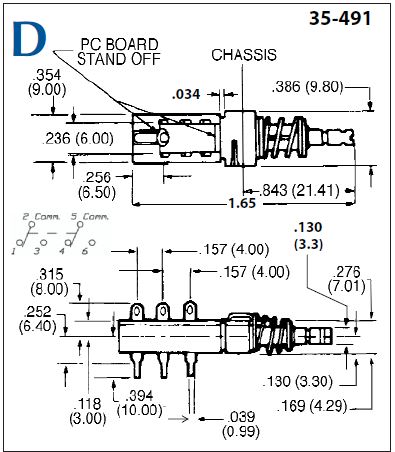
Sizes Power Switch Shutter Single
LED Op Panel Test Switch Function Pull Op Panel out front of system. Leave
PSU plugged in. Short 3-6 OR
5-4 and system should power up if Op Panel board and
cable are good. Nothing will happen if 5-6 or 3-4 are
shorted .
Replacement
Power Switch I had a 9585 that would not turn off reliably. You could push the switch up to five (or more!) times before it would turn off. I tried slowly wiggling the switch and the 85 would come up... LED
Panel Odd Behavior From Peter Alfred Arnold retorts And finally, the moment of discovery- Mod 95 with 8 "Lights" on
panel It suggests you pulled one end of the cable going to the LED display loose at one end or the other or that you somehow damaged the cable to it. Check for this small flat cable and make sure its OK. Jack, I had high hopes that it would be that simple. I checked and re-plugged both cables and did not change my symptom. Any other ideas. I have an HMM dated Sept 1993. Where did you find the symptom info.? Did you get it from the HM manual? From Jack GULLEY Panel Programs A small program to access the LED is HERE Bob Eager has these- BASIC Way A$ = "133 MHz " You can as well use DEBUG's "OUT {portnumber} {value}" command to pipe into the display. Write a text that includes 8 lines of out-commands to the ports 108 - 10F with the hex character values for {value} and use DEBUG<mytext.txt to bring it into the panel. 30 is "0", 39 is "9", 41 = "A" 5A = "Z" ... you will get the scheme. Linuxinfo Operator Panel Connector
Op Panel Presence Detect Codes Tomas Slavotinek Before I forget (again...), here is some more info about the Op Panel presence detect logic of the 9595 2S2P planar. It's actually even more primitive than I originally thought. There are no pullups and inverters on the planar. The pins are simply "floating low" (logic 0), and pullup(s) on the Op Panel and Multimedia Panel are used to force the bits high (logic 1). This unfortunately means that the 9595 2S2P planar can't differentiate between the older 9595 Op Panel (the one w/o HD LED) and the 9585 Indicator Panel. (Pins that are floating low, won't change their state when left floating or when grounded.) It can only detect the newer 9595 Op Panel and the unreleased Multimedia board that would connect to the unpopulated Multimedia Link connector. The Presence Detect bits 0, 1, and 3 are occupying pins 14, 12, 10, and 8 in that order. As can be seen here: http://www.ardent-tool.com/9585_9595/Op_Panel.html#95A_Pinout The four PD bits can be obtained via the Planar POS register cluster in 4 simple steps: 1) enable Group 1 Planar registers (set bit 7 of port 94h to 0) 2) select the Operator panel information ("Index 7" = 1Dh to port 103h) 3) read the Operator panel present info (low 4 bits) 4) disable Group 1 Planar regs (set bit 7 of port 94h back to 1) The mapping is straightforward: -PD 0 (pin 14) is mapped to the least sig. bit - bit 0 of reg 103h -PD 1 (pin 12) to 103h bit 1 -PD 2 (pin 10) to 103h bit 2 -PD 3 (pin 8) to 103h bit 3 There are no inverters, so unconnected or grounded pins will show as 0. Pins tied to +5V via pullups will show as 1. 95 / 85 Op Panel Presence Detect Codes: "0000" -the older 8595 Op Panel "0000" -the 9585 Indicator Panel "1000" -the newer 9595 Op Panel (pin 8 tied to 5V on the panel board) 95A Op Panel Presence Detect Codes: -the newer 95A Op Panel with the Multimedia board will come up as "1xy0" where "x" depends on the state of the Multimedia Link pin 1, and "y" on the state of the Multimedia Link pin 3. This gives us 3 other possible values: "1100" -95A Op Panel with MML pin 1 tied to 5V "1010" -95A Op Panel with MML pin 3 tied to 5V "1110" -95A Op Panel with MML pins 1 and 3 tied to 5V The T4 SurePath BIOS only uses this when Int 15 function CBh ("LED display - print character at position") is called. It will return 86h - "Not supported" if the function is called on a 2S2P 9595 that doesn't have the newer Op Panel connected to it. The older 1S1P planar doesn't have the Presence Detect logic at all, so the BIOS assumes that the panel is connected and blindly outputs the data to ports 108 - 10Fh. The POST routine doesn't actually check the Presence Detect bits it seems. NOTE: One could use the MML pins 1 and 3 as a cheap GPIO ports... You would have to poll it, and it's just GPI without the O part. Debugging comes to mind as one potential use. It may be useful for our BIOS experiments - to switch between two different code paths or whatever. Devkits/devboards often have a set of GPIO ports (sometimes hardwired to switches and LEDs) for this very purpose. 95A Audio Stage Schematic Peter wrote: To get a better output the R5 resistor could -probably- been bridged by e.g. a 220K resistor, which *should* result in a higher over all gain, but I don't know what's the output impedance of the audio sum node. It might be better to directly set the amp gain control pin 8 to pin 1 with a 10µF / 10K RC combo. That should result in a total amp gain of about 30 (20 = 26dB if 1 & 8 are open, 200 = 46dB if only a 10µF is used). Or altering the voltage divider R5 / R3 might also help. Given the signal source is 5Vpp @ 162KOhm load, the voltage at pin 3 is currently 0.068Vpp. At 26dB amplification the output is 1.35V for the normal linear amplification outside the frequency range when the bass boost is effective. ***********************************************************************
|