|
@6127.adf Future Domain MCS-700 / MCS-600 with TMC-1800 chipset @60E9.adf- IBM PS/2 SCSI-2 with TMC-18C50 chipset @5F77.adf Future Domain MCS-350 (no discrete SCSI controller chip! Uses PALs) IBM SCSI-2 Adapter/A Option Disk v1.00 For IBM/FD SCSI-2 Descriptor files for the MCS-350, MCS-600 and MCS-700 powrscsi.exe PowerSCSI powscsi4.exe PowerSCSI4 Future Domain's SCSI Device Analyzer IBM BIOS v1.01 for FD MCS-700 card used in PS/2 Model 77s. 27C64-200 FD MCS700 BIOS 3.61 Future Domain MCS700 v3.61. 27C64-200 1047000 221 POST code is caused by running a Patriot with nothing attached. You might see an I9990303 as well if the Patriot has kicked an IBM SCSI controller with the system partition out of the way, which is really confusing when you have a Type 4 Flash based complex installed... I fixed this problem with an Autoconfigure. Then the system booted normally... 5,544,326 Interface and control circuit for regulating data flow in a SCSI initiator with multiple host bus interface selection (18C50 used on FD MCS-700 / IBM Patriot) Design of the software interface for a multimaster bus system The Future Domain Story Long MCS-700 (TMC-1800 Based) MCS-600/700 or IBM SCSI-2 Install MCS-600/77/SCSI-2 Under W95 SCSI-2 on IML System Lacuna Convenience Partition FD and IBM Card Differences FD/SCSI-2 and P70 ESDI Running with the Devil (FD without ROM) MCS-600 and the DB25 Drive Shows up as "Direct Access" (Use FDDSU.EXE) MCS-600/700 TMC-1800 ADF Sections MCS-600/700 or IBM SCSI-2 (18C50 chipset) ADF Section MCS-350 MCS-350 ADF Sections MCS-200 The SCSI-2 Adapter /A was OEM'd by Future
Domain, based on the MCS-700. Early Future Domain
branded MCS-700 SCSI controllers may
use the TMC-1800 SCSI controller AND the termination
resistor arrangement of the MCS-600. The MCS-700 / 600
can do Narrow-Fast of up to 10MB/s to the SCSI bus
-BUT- only 3MB/s to the MCA bus. Please remember the
Future Domain was designed (successfully!)
to be a secondary SCSI adapter.
Future
Domain Ships Trio of Single-Chip SCSI-II Adapters "Boards
based on the chip can implement MFM-compatible BIOS
parameters, allowing AT or MCA computers to interact
with SCSI drives as if they were standard MFM hard
drives. This capability will allow use of products
such as PC Kwik disk caching (Multisoft) or Speedstor
(Storage Dimensions) that modify drive parameter. " 18C50 vs 1800 Based Adapters
> What are the differences between the TMC-1800 and
TMC-18C50? The external SCSI connection was a high-density DB-50
instead of the 'Apple' DB-25 connection of the MCS-600.
Shrouded internal SCSI connector (helpful for the right
orientation every time) & un-implemented solder pads
for jumper settings than could adjust some SCSI bus
options on the MCS-700 as well (artifacts for floppy?
The FD ISA SCSI-2 has similar jumper block). The MCS-700
power connector was more conservatively rated at 1.5
amps for the 12VDC and 5VDC pins, versus the 2 amp
rating on the MCS-600. Of course "C" in the chipset
number means the power-saving CMOS fabrication. I have to see if these different
chipsets return different values for the Future
Domain BIOS call "Get SCSI Controller Information" INT
13h, Function 18h. The book I have shows only values for
the older FD chipsets. There is another BIOS call that
determines ANSI SCSI-1 or SCSI-2 compatibility. Of
course the TMS-700 will have a much newer BIOS as well.
On the versions I have the boards are remarkably similar
despite the 3 year difference in production. Tiny
differences that add up on the finer points of
manufacture.
The FD design is PIO, not a busmaster. If you have a heavily loaded system, or one with low powered CPU, you might look for a busmaster. If you have a 486DX class system (or above) chances are the PIO will work just fine, because the CPU has more than enough clock cycles to service it. Long MCS-700 (TMC-1800) 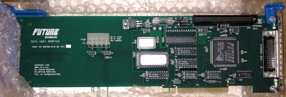 U4 appears to be a Micron MT5C6408-20? MT5C6408 8K x 8 SRAM datasheet same size and speed as with the Patriot... High speed, 20ns. Outline and through holes for a .600 wide DIP, and it is populated with a .300 DIP. TMC-1800. Production around 9026. Huh, BIOS is undated, "MCS-700 V1.1", the MCS-700 TMC-18C50 based controllers start with 3.2 and go up to 3.61 W2 is fully populated.... Four jumpers. Huh. The later short MCS-700 / Patriots have solder pads for a 4 jumper header. It might be to set SCSI options on the TMC-1800 chip, but not needed on the TMC-18C50... W1 is most likely TERMPWR. LT1086CT voltage regulator. The long MCS-700 is uncommon. Nice for collectors, but not too much, with the butt-load of short MCS-700 / Patriots... Plus it uses the slightly buggy TMC-1800 controller, the 18C50 fixed a few problems.
IBM SCSI-2 
U2 - NS
NMC27C64Q-200 65,536-Bit (8192 x 8) CMOS EPROM datasheet Jim Shorney pulls a few out of the weeds and says: Alternate for U4 - CY7C185-20 - 8Kx8 static RAM.
See here:
TERMENA Enables integrated
terminating-resistor. Remove if
both INTERNAL and EXTERNAL SCSI -
devices are connected. TERMPWR Enables
terminating-resistor voltage and should normally left in
place. W? is for ISA
version to set I/O and Memory Base Address
Four pins designated SWO-SW3 on FIG. 3 are provided to select the I/O and memory base addresses. In a microchannel implementation these four pins correspond to the microchannel POS bits 4-7. The I/O base address is given by Table I below and the memory base address is given by Table II below. A 1 in the Tables below corresponds to a grounded SWO-SW3 pin and a 0 corresponds to an open or pulled-up pin. Address bits 17 and higher are decoded by logic external to the multifunction SCSI chip.
Passive/Active SCSI
Terminating SCSI-2
on IML System Lacuna Convenience Partition
That's what I said. The system partition will not work with the *original* Future Domain MCS-700 without the "IBM Support BIOS" .... It works on the IDE-machines (utilizing the IBM Int4B ABIOS extension hooked to generic Bios Int13h -which is the boot / harddisk interrupt- ... attached to hardware IRQ 0Eh) and on the SCSI Models only with the reworked IBM controller BIOS. Reason why (to my opinion): the FD-controller can utilize other hardware IRQs than only 0Eh (14). My 9577-BTG has the IBM-version MCS-700 with the Rom
BIOS 1.01 (I think) and it has the "convenience
partition" as well. I had the cached SCSI in that
machine as well - it also supports the partition, but is
officially not supported in the Lacunas. MCS-600 and the DB25 Al Savage confided to the group: Um, only the DB25 (early SCSI-1) used only one wire per data line, with a combined data ground (unless I'm wrong). All the other SCSI wiring uses a separate ground for every data line, which is why I sold off all my DB25 stuff and went C50 everywhere. MCS-600 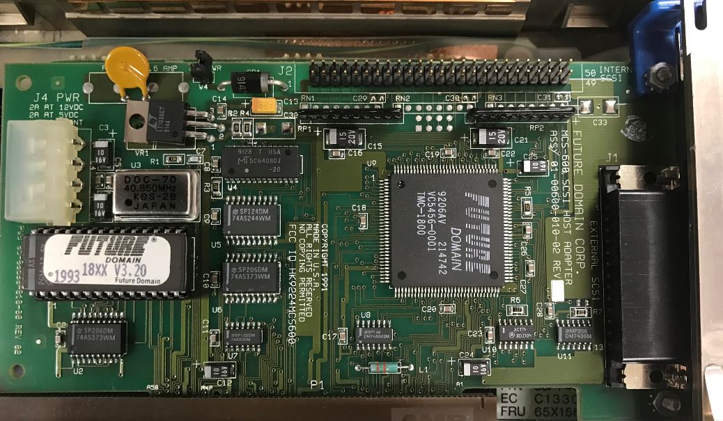 This shows the MCS-600 with a TMC-1800, no active termination, DB25 external port, unshrouded 50 pin internal header, uses a 40.850MHz osc, and has a 12v 2A and 5v 2A rating (the SMD caps are 10u, 16v) MCS-600/700 or IBM SCSI-2 under W95 Chances are, W9x won't get it right, and you might get a Future Domain TMC-16xx series adapter installed. Which works, but not the best. Manual install- Make sure the FD/SCSI-2 settings from
under IBM's system programs (refdisk or setup as you
want to call it) are used. W95 knows the choices
available. Make sure the I/O and IRQ are correct! If
not, you won't see a CD-Rom. FD and IBM BIOS Differences Tim Clarke tossed this out- For the Future Domain MCS-600/700 adapter ROMs - a) Future Domain V3.nn = Future Domain and
supports Int 13h via Int 4Ch (SCSI-CAM). Does boot-drive
scan from ID 0-6. (Peter)... but does not support IBM's
ABIOS functions which use Int 4Bh, which is the one that
establishes / handles a "convenience / reference
partition". And which is the function that reports back
the attached SCSI devices. Max drive size directly
controllable with the latest Future Domain BIOS (v3.61,
IIRC) it's around the 8GB mark (actually 8064MB), as
limited by the Int 13h BIOS call parameters' max. values
(1024-cylinders x 256-heads x 63-sectors x 512-byte
sectors). a1) Future Domain v3.4 - v3.5 (Reported by Cameron
Labut) The system would boot with the XGA1/512KB, HDs and
CDROM accessible. He swapped in an XGA2 (1MB stock) and
the HDs were inaccessible (but shows up on FD boot
message). CDROM is still accessible. This happened with
the original 8580 refdisk and with the refdisk patched
with XGAOPT.EXE . No XGA2 error messages were displayed
during POST, and the XGA2 passed advanced diagnostics... After swapping in an IBM Patriot 1.01 BIOS, the XGA2
and all SCSI devices were accessible at boot. Ed. As we totally lack either the 18C50 or Future Domain BIOS references, we can't be sure what the incompatibility is from. The incompatibility is most likely NOT Busmaster related, since the 512KB XGA1 co-existed with the MCS-700. Since the MCS-700 is PIO, that removes another possible conflict. No XGA2 error messages suggest that the patched refdisk files are compatible with the XGA2 BIOS / hardware. The only thing not fully explored is IF a FD MCS-700
w/3.4 and XGA1 w/1MB was unable to access HDs. Hours
spendt scouring the internet only provided ONE possible
significant issue, that of HD ordering. This does not
mean the HD ordering was the only issue with V3.4, but
suggest that V3.4 had issues. Future
Domain BIOS 3.4 and 3.5 Hard Drive ordering b) IBM V1.0n = Supports Int 13h via Int 4Bh (IBM SCSI). Does boot-drive scan from Id. 6-0 and supports RefDisk Config and Diags. If using the IBM v1.01 BIOS, it has a max drive size of 3.94GB (1024-cylinders x 255-heads x 63-sectors x 512-byte sectors), again IIRC. > For using the MCS-700 as a secondary controller, allowing drivers to be loaded, how big can the secondary drive be? This is only limited by the driver's and OS's design, but has limits set by a 32-bit "Logical Block Address" (LBA) of 4 Gigablocks and the assumed 512-byte logical block size = 2 terabytes. Check your OS doc.s and any READMEs for the driver for that OS. (Peter) I'd tried that on a machine with IBM
Controller BIOS Rev. 1.0 and the system refused to even
recognize the CD-ROM. I switched to a 1.01 controller
and -voilá- there it was. However: when I set the CD-ROM
to "Slave" it failed to work properly even with 1.01 on
the SCSI controller. There seem to be dependencies within the Boot-BIOS part of the IBM SCSI Bios on the FD-controller. 1.01 works fine with bigger HDs and CDs ... but dislikes CD-ROMs solely attached to the IDE jumpered as "Slave". Finally, Peter sez: Future Domain MCA SCSI Adapter BIOS versions 18MC means 1800, otherwise the table wraps BOARD BIOS After surfing ebuy, I see that the 18C30 and 18C50 both use the V3.x BIOS. The 18C30/50 use a mix of BIOS levels, for instance, there was a TMC-1660, 18C30 with a V3.5 (94) BIOS. There was a TMC-1660, 18C50 with a V3.01PM (92) BIOS. To guess, the 18C30 is a simple version of the 18C50. Dunno. V3.01PM 92 (OEM for Pinnacle) V3.20 93 V3.3 93 V3.4 94 V3.5 94 Long MCS-700 (TMC-1800) BIOS The Long MCS-700 (TMC-1800 controller) has an undated BIOS "V1.1 MCS-700", I would guess about 1992? SCSI-2
and P70 ESDI Adventures The ROM version on the MCS-700 is 1.01. I've tried it in both slots as well as tried changing the IRQ and such in the Reference disk setup. All of this had no effect on the error. 1) reinstalled the MCS-700 with the IBM
BIOS 1.01 still installed. It continued to give the
error and I ran diagnostics from the Refdisk. The
SCSI test gave an error of 0210000U. 2) I removed the BIOS and reinstalled. PowerSCSI4 would not install without a device hooked to the card so I connected an external 1gig SCSI hard disk to it. Drivers installed fine under both DOS and OS/2. No errors on boot and I'm able to access the drive fine under both operating systems as well. It took 4-1/2 minutes to copy 64meg of data from the internal DBA disk to the external SCSI disk. I had tried to disable the BIOS in the system setup on the Refdisk, but it didn't help. Removing the BIOS chip altogether seems to have fixed it though. My only complaint is that it insists on formatting the external hard disk with 32k sectors! I'll have to play with that some more. Now the question is, what functionality have I lost by removing the BIOS chip? Am I correct to assume that it won't be possible to boot off a SCSI disk in this configuration? FD
w/o ROM Tim Clarke ADF File for MCS-600/700 board (TMC-1800 VLSI) Version 1.1 AdapterID 06127h Future Domain SCSI Adapter Adapter Memory Location
Adapter I/O Location
Select Interrupt Line
ADF File for MCS-700 /IBM MC
SCSI-2 adapter (18C50
VLSI) Adapter ROM BIOS Address
Adapter I/O Port Address
SCSI Adapter Address (ID)
Select Interrupt Line
Direct Access Fix? >I've tried to add a 2GB 0664 drive as ID4 to my system. The added drive at ID 4 is listed as "direct access" instead of "hard disk," and no size is listed. When I attempt to low-level format, the list of available drives does not include the drive at ID 4. Can someone please tell how to revive the 0664 that responds as a "direct access" device??? The Magic Christian responds: 'The following procedure should read the firmware parameters from a SCSI drive and then write those parameters back to the media. This will normally restore a fixed disk to the factory default parameters. Not all drives will support this procedure. Future Domain will not be responsible for the results stemming from the use or misuse of this procedure. 1. Insert the Future Domain "SETUP" utility. This should update the media with the
parameters from the firmware. The drive must accept and
finish the low-level format for the above procedure to
work correctly. Also, some drives do not support a
low-level format. When in doubt check with the drive
manufacturer. " Specs PS/2 SCSI-2 Adapter/A and MCS-700
OS/2
Switches BASEDEV= ---- FD8XX.ADD
-------------------------------------- MCS-350 
U12 UM6116-3
Unicorn Microelectronics 2K x 8 CMOS SRAM datasheet
After looking at an MCS-350, there is no discrete SCSI
controller. I >assume< the controller
functionality is within one or more PALs. AdapterID 5F77 Future Domain SCSI Adapter Memory Location DMA Arbitration Level
Select Interrupt Line
Use Front Panel Disk Busy
Light Use MC BUS Wait (IBM Model 80)
MCS-200 (Also Quantum MC-200S) 
U4 Toshiba TC5588J-20 or ATT 7C185J-20 Termpwr Fuse |