Identify SIMMs
(Presence Detect and Chip Configuration)

Memory-Module Kit Identification
72 pin SIMM Identification with a DMM
Resistor to PD Bit
PD Bits to Memory Size / Speed Codes, Parity
SIMMulator (Socketed PD Tester, cheap!)

PS/1, PS/2, and PC Memory Reference

Memory-Module Kit Identification
Some early memory module kits are not labeled with a FRU number. The following information provides methods of identification.

There are four key identifiers:
   1. Chip size: narrow or wide
   2. Chip placement (horizontal, vertical, both, 1 side or 2 sides)
   3. Speed suffix shown on the individual chips (7=70ns, 8=80ns, 85=85ns)
   4. Module ID resistors (R1=85ns, R2=80ns)

Memory-Module Kit 1A and 1B

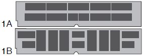
Kit 1A and 1B, show 10 or more chips mounted horizontally, vertically or a mixed pattern. If there are chips on one side of the board, it is 1MB. If there are chips on both sides, it is 2MB. (A small number of 8MB kits were also manufactured in this configuration.) The suffix on the chip, for example, -8, -85 is important.

Memory-Module Kit 2L and 2R


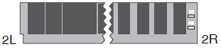
Kit 2L shows 10 wide chips with resistors across the top, but not on the end. If there are chips on one side, it is 4MB; two sides it is 8MB.

Kit 2R shows 9 or 10 chips per side, all mounted vertically. If there are two resistor locations on the right end labeled R1 and R2, it is 2MB. (R1 = 85ns, R2 = 80ns, R1 + R2 =
100ns.) There will either be 9 or 10 chips.

Memory-Module Kit 3


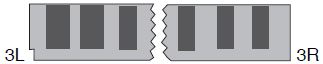
Kit 3 has 6 chips per side spaced evenly. If all the chips are the same size, (3R) it is 1MB. If the two center chips are smaller than the 4 outer chips, (3L) it is 4MB. These could be any speed.

Memory-Module Kit 4A and 4B


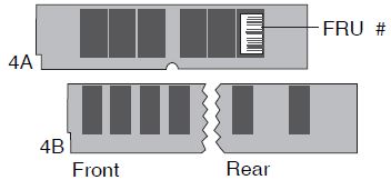
Kit 4A and 4B are both 4MB. 4A has 6 closely spaced chips on each side. There are no resistors, and it is 85ns (there might be a tiny FRU number on the end chip.) 4B shows the front and rear of another 4MB chip configuration. There are 8 chips on the front, and 4 on the rear.

72 pin SIMM Identification when no Shunts Are Visible
From the PC and PS/2 Pocket Reference Manual, Feb 1996-
  The presence detect pins 67-70 tell the system the size and speed of the IBM standard 72 pin parity SIMMs. Using good ESD procedures and a digital Volt/ohm meter, measure the resistance between pins 67-70 and 72 which is ground. (R1, R2, etc)

The presence-detect signals are used by the system to determine the size and speed of memory on the memory module. The pins are either not connected or connected to ground.

NOTE: Test Pin 72 to Pins 70, 69, 68, and 67. Though you can probe the PD resistors to pin 72, you can be on the wrong side, giving you multiple erroneous readings....

Memory Presence Detection for College Graduates
 

For years, I have been living easy with the Models 90 and 95, both use 70nS FPM SIMMs, which are fairly common. But when faced with a 8573-P70, I was brought to my knees by it's demands for ONLY a 2MB 85nS SIMM. Many of the older SIMMs are marked only with a P/N, the size and speed are not shown. Even worse, many individual IBM chips are marked only with IBM P/Ns... These chips lack 
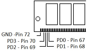
even a speed rating.

When you look at a SIMM, the notch is to the right. Pin 72 will be the leftmost pin (usually silk screened or part of PCB).

Pin - PD Bit - Resistor #
Note that the Resistor numbers (R1, R2...) are in reverse to the PD bit number.

Pin
PD Bit
R#
70
PD3
R1
69
PD2
R2
68
PD1
R3
67
PD0
R4

PD Bits to Memory Size / Speed Codes, Parity
Note that the PD bits are binary, with LSB to the right (Pin 67)

Pin 72 to Pin 70, 69, 68 and 67 ( o is open, X = connected to GND via 0 ohm resistor)

PD Bits
3 2 1 0

70

69

68

67

SIMM Definition

1101

o

o

X

o

32MB 60-ns Industry

1001

o

X

X

o

32MB 70-ns Industry

0101

X

o

X

o

32MB 80-ns Industry

1110

o

o

o

X

16MB 60-ns Industry

1010

o

X

o

X

16MB 70-ns IBM / Industry

0110

X

o

o

X

16MB 80-ns Industry

1011

o

X

o

o

8MB 70-ns IBM / Industry

1000

o

X

X

X

8MB 80-ns IBM / Industry

1000

o

X

X

X

4MB 70-ns Industry

0100

X

o

X

X

4MB 70-ns IBM

0100

X

o

X

X

4MB 80-ns Industry

0000

X

X

X

X

4MB 80-ns IBM

1001

o

X

X

o

2MB 70-ns Industry

1100

o

o

X

X

2MB 70-ns IBM

0101

X

o

X

o

2MB 80-ns Industry

1001

o

X

X

o

2MB 80-ns IBM

0101

X

o

X

o

2MB 85-ns IBM

1110

o

o

o

X

2MB 100-ns IBM

1010

o

X

o

X

1MB 70-ns Industry

0110

X

o

o

X

1MB 80-ns Industry

0110

X

o

o

X

1MB 85-ns IBM

0010

X

X

o

X

1MB 100-ns IBM

1111

o

o

o

o

Connector is empty

Notes:
Note that some Industry standard PD codes are the same as IBM's, yet differ in speed.
Some systems "mask" PD bits, ex. the 8573-P70 masks PD0 and PD1


If the PD Shunts are Visible
A set of four bits shows the state of the presence-detect signals for a specific memory connector; a bit is 0 when the signal is connected to ground by the memory module. 

Thanks Peter! 
Presence Detect Signals
ECC/PAR (Pin 48)         --------------------------  -+ 
PD Bit0 (Pin 67)        ------------------+           | 
PD Bit1 (Pin 68)        ----------------+ |           | 
PD Bit2 (Pin 69)        --------------+ | |           | 
PD Bit3 (Pin 70)        ------------+ | | |           | 
GND     (Pin 72)        --------+   | | | |           | 
                                |   | | | |           | 
                                V   V V V V           V 
                        +-------------------------   ---   ---------+ 
                        |       # # # # # # # # #..   #  .. # # #   | 
                        |       # # # # # # # # #     #     # # #   | 
                        |                                           | 
                        |       7 7 7 6 6 6 6 6 6     4     0 0 0   +-+ 
                        |       2 1 0 9 8 7 6 5 4     8     3 2 1     | 


SIMMulator
Jim Shorney sez:
   Whacked the end SIMM socket off of an old Dell motherboard with a hacksaw and soldered up four LED's with 1K current limiting resistors to pins 67-70.  Feed it 9 to 12 volts DC against pin 72, and it makes a nice PD code reader for aSIMMilating those unidentified memory modules into the proper baggie.  No more fumbling with an ohmmeter.

Tony Ingenoso has a safety announcement:
   Sacrifice a clone mobo for the socket.  A propane torch from the rear will usually drop 'em off pretty clean.  Gotta burn through the little attach pegs, but once that's done they drop right off...
   A pail of water is nice to have standing by.  Sometimes the boards light up pretty good and really start stinking and billowing clouds of black smoke. Don't want the neighbors to call the FD ;->  

9595 Main Page