Floppy Drive Interface Pinouts
The rising champion of Micro Channel, Tomáš Slavotínek,
hefted his mighty multimeter, bellowed his defiance to the
dark gods of Obscurity and Uncertainty, and hewed
down some mighty servants of Kaos.
He verified some pinouts and cranked out some graphical
depictions of some common floppy cables.
40-Pin
Card-Edge Interface
34-pin Header
Interface (Non-Media Sense)
Enhanced 34-pin
Header Interface (Media Sense)
40-pin
Planar Interface (95 XP)
44-pin
Planar Interface (95A, Lacuna, 85K/N)
PS/2 Floppy Drive Connectors
Signals and voltages are transferred
between the system board
and the diskette drives by a cable or printed circuit
board. The printed-circuit
board provides a 2- by 20-pin card edge connector for
each diskette drive,
with a locator key between pins 34 and 36. The cable
interface provides
a 2 x 17-pin header connector to each diskette drive,
with a locator key
below pin 17. The following tables show the signals and
DC voltages
for each diskette drive connector type.
Extracted from PS/2
3.5-inch Diskette Drives Technical Reference
(S42G-2194-00),
2nd Ed., Oct 1992, pages 10-12. (Unless noted
otherwise.)
NOTE: There are
differences between
the 1990 Tech Ref and the '92 Tech Ref Signal names for
the Enhanced 34-pin
interface. See the Notes below the table. I believe the
additional definition
is related to the floppy controller used for the EE
floppies.
40-Pin Card-Edge Interface
| Pin |
Signal |
Pin |
Signal |
| 1 |
Ground |
2 |
-High Density Select |
| 3 |
Reserved |
4 |
Reserved |
| 5 |
Ground |
6 |
Reserved |
| 7 |
Ground |
8 |
-Index |
| 9 |
Ground |
10 |
Reserved |
| 11 |
Ground |
12 |
-Drive Select |
| 13 |
Ground |
14 |
Reserved |
| 15 |
Ground |
16 |
-Motor Enable |
| 17 |
Ground |
16 |
-Direction In |
| 19 |
Ground |
20 |
-Step |
| 21 |
Ground |
22 |
-Write Data |
| 23 |
Ground |
24 |
-Write Enable |
| 25 |
Ground |
26 |
-Track 0 |
| 27 |
Ground |
26 |
-Write Protect |
| 29 |
Ground |
30 |
-Read Data |
| 31 |
Ground |
32 |
-Head 1 Select |
| 33 |
Ground |
34 |
-Diskette Change |
| 35 |
Ground |
36 |
Ground |
| 37 |
Ground |
36 |
+5VDC |
| 39 |
Ground |
40 |
+12VDC |
34-pin Header Interface
(Non-Media Sense)
This connector is for drives and
controllers that do not support media sense.
| Pin |
Signal |
Pin |
Signal |
| 1 |
Ground |
2 |
-High Density Select |
| 3 |
+ 5VDC |
4 |
Drive Type ID 1 |
| 5 |
Ground |
6 |
+ 12VDC |
| 7 |
Ground |
8 |
-Index |
| 9 |
Ground |
10 |
Reserved |
| 11 |
Ground |
12 |
-Drive Select |
| 13 |
Ground |
14 |
Reserved |
| 15 |
Ground |
16 |
-Motor Enable |
| 17 |
Ground |
18 |
-Direction In |
| 19 |
Ground |
20 |
-Step |
| 21 |
Ground |
22 |
-Write Data |
| 23 |
Ground |
24 |
-Write Enable |
| 25 |
Ground |
26 |
-Track 0 |
| 27 |
Ground |
28 |
-Write Protect |
| 29 |
Ground |
30 |
-Read Data |
| 31 |
Ground |
32 |
-Head 1 Select |
| 33 |
Ground |
34 |
-Diskette Change |
Enhanced 34-pin Header
Interface (Media Sense)
This connector is for drives and
controllers that support media sense.
| Pin |
Signal |
Pin |
Signal |
| 1 |
Ground |
2 |
Data rate Select 1 |
| 3 |
+ 5VDC |
4 |
Drive Type ID1/Drive
status 1 |
| 5 |
Ground |
6 |
+ 12VDC |
| 7 |
Ground |
8 |
-Index |
| 9 |
Drive Type ID0/Drive
status 0 |
10 |
Reserved |
| 11 |
Ground |
12 |
-Drive Select |
| 13 |
Ground |
14 |
-Security Command * |
| 15 |
Ground |
16 |
-Motor Enable |
| 17 |
Media Type ID1/Drive
status 3 |
18 |
-Direction In |
| 19 |
Ground |
20 |
-Step |
| 21 |
Ground |
22 |
-Write Data |
| 23 |
Ground |
24 |
-Write Enable |
| 25 |
Ground |
26 |
-Track 0 |
| 27 |
Media Type ID0/Drive
status 2 |
28 |
-Write Protect |
| 29 |
Ground |
30 |
-Read Data |
| 31 |
Ground |
32 |
-Head 1 Select |
| 33 |
Data rate Select 0 |
34 |
-Diskette Change |
All blue text is not
present in '90 Tech. Ref.
* Not supported by all
drives or all systems.
'90 Tech. Ref. has this Reserved.
40-pin Planar Diskette
Interface
This connector is found on the 90 XP and
95 XP planar.
| Pin |
Signal |
Pin |
Signal |
| 1 |
-2nd Drive installed [D0 & D1 pin 1] |
2 |
Data rate Select 1 |
| 3 |
+ 5VDC |
4 |
Drive Type ID1 |
| 5 |
Ground |
6 |
+ 12VDC |
| 7 |
Ground |
8 |
-Index |
| 9 |
Drive Type ID0 |
10 |
-Motor Enable 1 [D0 pin
16] |
| 11 |
Ground |
12 |
-Drive Select 0 [D1 pin
12] |
| 13 |
Ground |
14 |
-Drive Select 1 [D0 pin
12] |
| 15 |
Ground |
16 |
-Motor Enable 0 [D1 pin
16] |
| 17 |
Media Type ID1 |
18 |
-Direction In |
| 19 |
Ground |
20 |
-Step |
| 21 |
Ground |
22 |
-Write Data |
| 23 |
Ground |
24 |
-Write Enable |
| 25 |
Ground |
26 |
-Track 0 |
| 27 |
Media Type ID0 |
28 |
-Write Protect |
| 29 |
Ground |
30 |
-Read Data |
| 31 |
Ground |
32 |
-Head 1 Select |
| 33 |
Data rate Select 0 |
34 |
-Diskette Change |
| 35 |
Ground |
36 |
Drive Select 2 [D2 pin
12] |
| 37 |
Ground |
38 |
Ground |
| 39 |
Ground |
40 |
-Motor Enable 2 [D2 pin
16] |
Signals not intended for all drives are marked as such
by a note in [square brackets].
Information not available in any tech. reference I
have access to. So I
have used the known 34-pin floppy drive pinout, the
actual 40-pin 95 XP
floppy cable, and some measurement results to figure
this out.
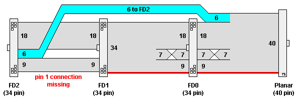
40-pin Floppy Cable Wiring Diagram (Model 95 XP,
FRU 33F8430)

| Planar |
FD0 |
FD1 |
FD2 |
| 1 |
1 |
1 |
- |
| 2-9 |
2-9 |
2-9 |
2-9 |
| 10 |
16 |
10 |
10 |
| 11 |
15 |
11 |
- |
| 12 |
14 |
12 |
- |
| 13 |
13 |
13 |
- |
| 14 |
12 |
14 |
- |
| 15 |
11 |
15 |
- |
| 16 |
10 |
16 |
- |
| 17-34 |
17-34 |
17-34 |
17-34 |
| 35-40 |
- |
- |
11-16 |
44-pin Planar Diskette
Interface
This connector is found on the 95A,
Lacuna, and 9585 K-N models.
All floppy drives used must support media sense.
| Pin |
Signal |
Pin |
Signal |
| 1 |
-2nd Drive installed [D0
& D1 pin 1] |
2 |
Data rate Select 1 |
| 3 |
+ 5VDC |
4 |
Drive Type ID1/Drive status 1 |
| 5 |
Ground |
6 |
+ 12VDC |
| 7 |
Ground |
8 |
-Index |
| 9 |
Drive Type ID0/Drive status 0 |
10 |
Reserved |
| 11 |
Ground |
12 |
-Drive Select 0 [D0 pin
12] |
| 13 |
Ground |
14 |
-Security Command 0 [D0
pin 14] |
| 15 |
Ground |
16 |
-Motor Enable 0 [D0 pin
16] |
| 17 |
Media Type ID1/Drive status 3 |
18 |
-Direction In |
| 19 |
Ground |
20 |
-Step |
| 21 |
Ground |
22 |
-Write Data |
| 23 |
Ground |
24 |
-Write Enable |
| 25 |
Ground |
26 |
-Track 0 |
| 27 |
Media Type ID0/Drive status 2 |
28 |
-Write Protect |
| 29 |
Ground |
30 |
-Read Data |
| 31 |
Ground |
32 |
-Head 1 Select |
| 33 |
Data rate Select 0 |
34 |
-Diskette Change |
| 35 |
Drive Select 1 [D1 pin
12] |
36 |
Ground |
| 37 |
-Security Command 1 [D1
pin 14] |
38 |
Ground |
| 39 |
-Motor Enable 1 [D1 pin
16] |
40 |
-Drive Select 2 [D2 pin
12] |
| 41 |
Ground |
42 |
-Security Command 2 [D2
pin 14] |
| 43 |
Ground |
44 |
-Motor Enable 2 [D2 pin
16] |
Signals not intended for all drives are marked as such
by a note in [square brackets].
Information extracted from IBM PS/2 Servers 95 and
95A Technical Reference,
Type 9595, page 2-5, First Ed., Sept 1993. P/N 71G3726
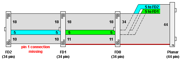
44-pin Floppy Cable Wiring Diagram (Model 95A,
FRU 92F0283)

| Planar |
FD0 |
FD1 |
FD2 |
| 1 |
1 |
1 |
- |
| 2-11 |
2-11 |
2-11 |
2-11 |
| 12-16 |
12-16 |
- |
- |
| 17-34 |
17-34 |
17-34 |
17-34 |
| 35-39 |
- |
12-16 |
- |
| 40-44 |
- |
- |
12-16 |
9595 Main
Page
|

