|
@EFDC.ADF
- IBM ActionMedia (TM) II Display Adapter/A
Software AM2DRV.EXE: v2.12 driver Win3.x, Indeo Video v2.12, YVU9 Video, PLV v2.0, AVS. AM2SET.EXE: (v2.10). Setup and configuration actmed2.exe Option disk from IBM AM2DOC.PDF: Hardware installation guide for ISA cards under Windows AM2SFTDC.PDF: AM2 Driver for Indeo Video Installation Guide for ISA /Windows amiiprog.zip AM II Programmer's Guide and Ref for MCI programming in MMPM/2 (source with library included) VfW11e SDK and runtime for 3.1x, 95, NT (AM2 works under 3.1x only...) AVI, MPG, WMV, MPEG Converter (and AVS!) Maybe... I have no experience with Total Movie Converter List of supported conversions AVS to AVI AVS to MPEG AVS to MPG AVS to WMV AVS to FLV i750 Video Processor Technical Specifications Oct90 82750PB and 82750DB 82750LA Keying and Audio Gate Array (KAGA) Technical Specifications 82750LH Host Interface Gate Array (HIGA) Technical Specifications 82750LV VRAM SCSI Capture Gate Array (VSCGA) Technical Specifications ADSP-2105 DSP Microcomputer datasheet ADV476KP35E CMOS 40 MHz 256x24 Color Palette RAM-DAC datasheet CS5338-KS 16-Bit, Stereo A/D Converters for Digital Audio Datasheet AVSAVI.EXE: Windows program which converts some AVS into AVI files. avsavi.txt Reame for AVSAVI.EXE am2os21.exe 558 Kb OS2 driver v1.2 1/2 am2os22.exe 450 Kb OS2 driver v1.2 2/2 Media Control Driver for MMPM/2 am2wav.rar ActionMedia II Wave Audio Device Driver 1.10 am2win1.exe 271 Kb Windows driver v1.2, 1/2 am2win2.exe 463 Kb Windows driver v1.2, 2/2 DVision Cineworks Person To Person (P2P) Page Person2Person for OS/2 * Possible Person 2 Person, ver 2.0? IMG format DVI Technology Products by Douglas Dixon Capturing Digital Video Using DVI Multimedia and the i750 video processor (Dr. Dobbs) Capturing DigitalVideo Using DVI (HTML version of above) Transport and Display Mechanisms For MM Conferencing Across Packet-Switched Nets Multimedia Playout Synchronization Using Buffer Level Control Tech notes
Intel DVI Multimedia Publications
ActionMedia Evolution Prototype Delivery and Capture Boards (82750PA/DA?) ActionMedia Delivery Board and Capture Board (82750PA/DA) ActionMedia 2 Delivery Board and Capture Option (82750PB/DB) Action Media II Delivery Card Setting Jumper E1 for Digital or Analog Keying Capture Card CS2 option standoff / spacers / support dimensions Install Capture Card Removing the AVE Contacts Further Thoughts on AVE Connector (Terminate unused RGB lines...) Configure ActionMedia/2 Under OS/2 with AM/2 Configuration Utility Connectors and Cables Video Cable connector (HDD-15) RGB Overlay Cable Attached (Analog Keying) Video Cable Pinout Auxiliary Video Output Connector (S-VHS / 4 pin DIN) Audio/Video Capture Cable Audio/Video Capture Connector Pinout (Female socket on AM2) Capture Cable Mini-DIN Plug Pinout (Male plug on 8 Way Mini-DIN) 69F9736 Complete The 8 way cable, S-VHS adapter, and two BNC to RCA adapters Connecting The Video Capture Source Composite Video Format S-Video Format RGB Composite Sync Format RGB Sync On Green Format Connecting The Audio Capture Source Audio Signal Cable ActionMedia/2 to M-ACPA Cable Power Usage Autoconfiguration Problems (Not present or disabled) Intel DS2 and IBM AM2 ADF Oddities ("Disabled" in "Extended Memory Window") False 10906x6 Error (Related to autoconfig issue!) ActionMedia/2 Error Codes ADF Sections ActionMedia Evolution Thanks to Lorenzo Mollicone, I was able to get evidence of the ActionMedia Prototype and the release version of the original ActionMedia. The images are not of uniform quality, and I cannot do a good job of component ID. The AM boards use a connector similar to that used on the Video Capture Adapter/A HERE and MAYBE the same pinout... ActionMedia Prototype Delivery Board 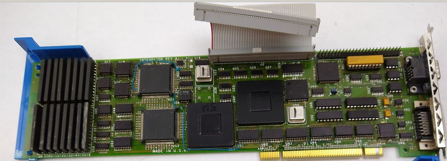 Looks like J1 is for a SCSI controller. It is the 50 pin header at upper right edge, with the resistor network below it. The 60 pin header (J2) in the center connects to the AM Prototype Capture Board below. Most likely card to card communications. Looks like one of the half-can oscillators was removed, see the solder tail sockets? See the AVE connector used to pick up Base Video? ActionMedia Prototype Capture Board 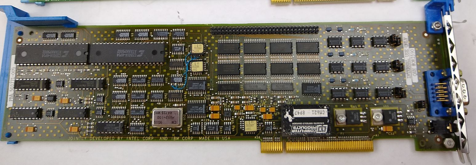 I don't have any pics of the connectors on the brackets, so if this is a DB9 or HDD15, I can't tell. Notice the 1/8 inch audio jack at the lower right. See the three sets of six pin headers towards the right side? See the three pin header to the left of the blue video port? My guess it is similar to E1 on the AM2, and is used to choose digital keying over the AVE on the Delivery card, or Analog keying, via a video cable attached to the video connector... Notice the pair of CS5014-KP1A at upper left corner? Full can oscillator shows a date of 9010. U52 is 12.44755 MHz (inking indistinct) ActionMedia Delivery Board 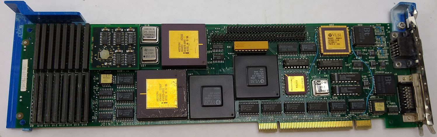 You can see the 82750PA and 82750DA. J1 (50 pin header) is now at top dead center. J2 (60 pin header) is right below it. Pair of Bt RAMDACs. I think the date code on the 82750PA is 9044. U18 25.0000 MHz, U27 14.3181 MHz, U47 33.868 ? damaged osc... ActionMedia 2 Delivery Card w/ Capture Option 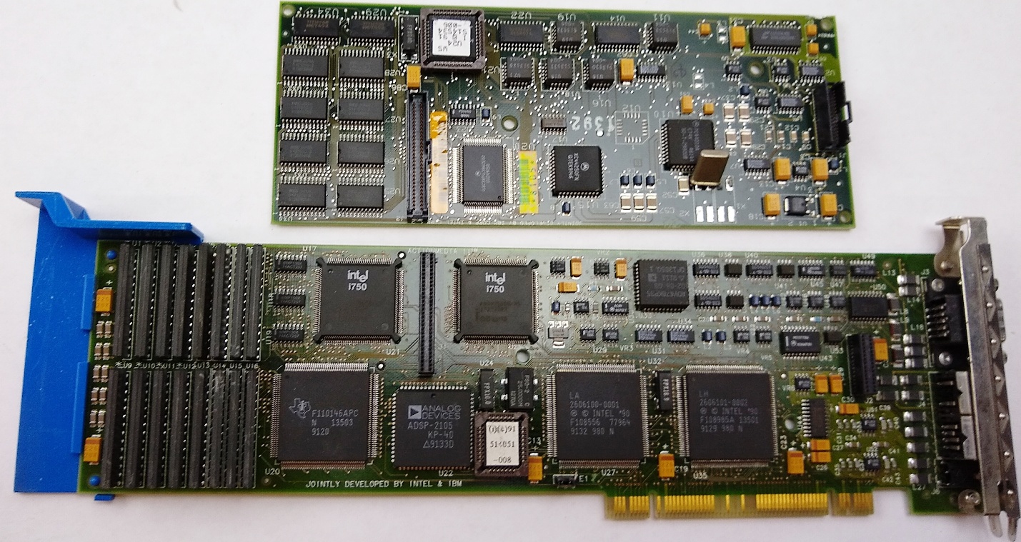 ActionMedia 2 Capture Option (CS2) dated 4791 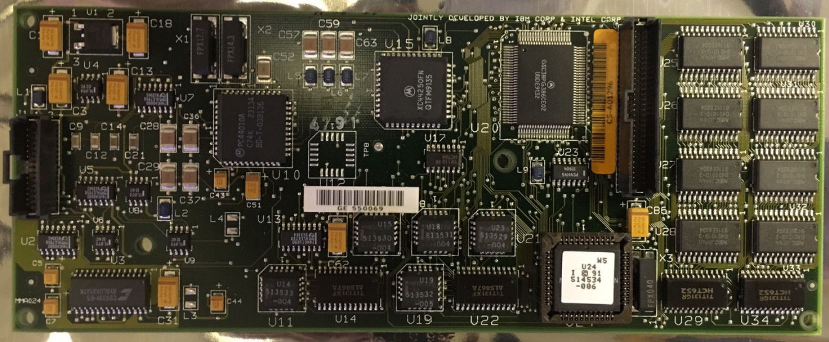 Grabbed this pic from Lorenzo Mollicone and it verifies my suspicions about X1 and X2. They are SMD xtals. X1 is FPX17.7 and X2 is FPX14.3 Please note that FPX040 is at the lower right corner of the socketed PLCC. All versions of the PLCC are © 91, 514536 -006. 4791 - X1, X2 SMD crystal, four solder pads per xtal. 1292 - X1, X2 radial lead cans, four solder pads per xtal. Case not soldered to solder pads by edge of PCB. X1 signal leads doglegged to solder pads. 1194 - X1, X2 xtals same locations, but no solder pads for xtals. Both signal leads stick straight out to through holes. Each xtal case is fastened by a single pin to a through hole. FPX Case and Side 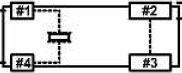  ActionMedia II Adapter/A Delivery
Card FRU 69F9733
/ PN 69F9732
Intel 82750PB Microcode Programming Guide Jumper Block E1 Digital Digital
keying via AVE / BVE
Analog vs Digital Keying
Removing
the AVE Connectors Fortified with desperation and caffeine, I figured that the AM/2 was to be used with the three port video cable, 69F9737, which means that I'm dealing with analog, so the need for digital keying is moot. NOTE: If you don't have the overlay cable, do NOT whack the AVE connector, as you are stuck with digital keying over the AVE / BVE connectors. I took an AM/2 which had complained of a serious error, cut the connector off, and tested it with advanced diagnostics. It passed all tests. The problems that it reported earlier were gone. I then altered another AM/2 and placed it into Slot 1. Configured without a hitch and passed advanced diagnostics. I used a pair of diagonal cutters, parallel to
the edgecard traces, and just snipped it off a little at
a time. I cut the remaining "tooth" off, then used an
X-Acto knife to whittle the ragged edge down. I didn't
worry about shorting out any traces or pulling them up
when I nipped and shaved my way to bliss. The green
solder resist is TOUGH and it holds everything in place.
Further
Contemplation on
the AVE Connector A note from the VCA/A: Capture
Card Also called
the CS-2 FRU 69F9735 / PN 69F9734
The earlier CS2 used SMD crystals, but they changed over to the can format.... CS2, 1194 single lead soldered to the top of each xtal case, connecting the case to ground. The two xtal leads run directly to the through holes and the through holes and leads are correctly spaced. CS2 option standoff / spacers / support dimensions: Sometimes you scrounge up a CS2 board, and the little nylon PCB standoffs are gone. Unfortunately, there is no hard and fast rule for naming these puppies. I see them as supports, spacers, posts, and possibly spacers. The AM2 and CS2 PCBs are .065" thick. The mounting hole IDs are @ .152" diameter. The distance between the AM2 and CS2 boards is 7/16" (.439"). 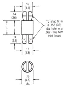 Posts - Miniature Model: 30353-N
This standoff was on a '94 production card. It was not as costly as a threaded nylon standoff. Looks to take a #6 machine screw (#6 holes are @ .146"). A threaded nylon post and matching #6 nylon screws would work. Now to find the 7/16 (.439") spacer length... Install Capture Card 
Single monitor configurations, operating in either VGA 640x480 non-interlaced or in XGA 1024x768 interlaced modes, are supported when the text and graphics information provided by the host PS/2 may be overlaid on the images provided by the AM2 display adapters. In these configurations, the keying of the overlay is controlled by the output of the host graphics adapter, such that a zero (black) output results in the host information becoming transparent to the images provided by the AM2. A dual-monitor configuration is also supported, with one monitor used for the host's graphics adapter and a second monitor used for the images provided by the AM2, but that does not allow any host text or graphics overlay. The AM2 Capture Option (CS2) extends the AM2's capabilities to include capturing and digitization of audio and of analog video input signals (either NTSC or PAL), allowing such signals to be monitored on the PS/2 display screen, captured as still frames, or compressed in real time using the DVI Technology Real Time Video capability. MACHINE REQUIREMENTS:
The
AM2 /A can be installed in PS/2 Models 8555, 8557, 8565,
8570, 8573*, 8580, 8590, 8595, and the 7546 Industrial
Computers. Use of the AM2 Audio Video Kernel
requires a minimum of 4MB of system memory. If
additional OS/2 applications are required to run in the
PS/2, then a minimum of 6MB of system memory is
recommended. Supported graphics adapter and
monitor cabling configurations : PROGRAMMING REQUIREMENTS:
IBM
OS/2 Version 1.3 required for installation of Audio
Video Kernel Version 1.0 device drivers. We have found a problem that causes a "Trap 8" (double protection exception) in the device driver "HWDDD$" which is part of ActionMedia II. The problem is caused by a configuration incompatibility with the 3270 connection card. The problem will typically be found when booting up OS/2 with both ActionMedia II, and the 3270 connection ver A card installed at interrupt level 9. The 3270 Connect ver A card
has only one interrupt level - 9. The ActionMedia
II 2MB/A card has three interrupts, audio, video and
capture.Video defaults to level 10, audio to level 10,
and capture to level 11. Audio and capture can be set to
level 10 or 11, and video to 9, 10, 11 or 12. ActionMedia/2
Video Cable Auxiliary
Video Ouptut Audio/Video
Capture Audio
Output
ActionMedia II Video Cable connector (Video Cable is FRU 69F9737) The AM2 Video Cable connector (15-pin) enables the AM2 Display Adapter/A to take the video signals from a normal PS/2 VGA or XGA display adapter, combine it with AM2 video signals, and send the mixed video signal to a PS/2 display. The presentation on the PS/2 display is developed from either: o VGA or XGA video signals, o ActionMedia II video signals, or o Mixed ActionMedia II and VGA or XGA video signals. The default is to pass VGA or XGA video signals to the PS/2 display. RGB
Overlay System (Analog Keying) Video
Cable Pinout FRU 69F9737 Base
(White)
Monitor
AMII (Black) Auxiliary Video Output Connector The Auxiliary Video Output Connector (4-way DIN) connects an AM2 Adapter to an S-VHS (also referred to as Y-C) video recorder or similar device. NOTE: ISA Installation Manual refers to this as an Input connector. YMMV.  Pin Signal Pin Signal 1 Y Video Gnd 3 Y Video Gnd 2 C Video Gnd 4 C Video Out S-VHS Capture Cable Female Connector Pinout 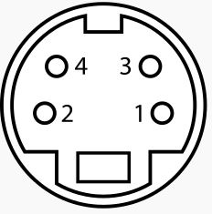
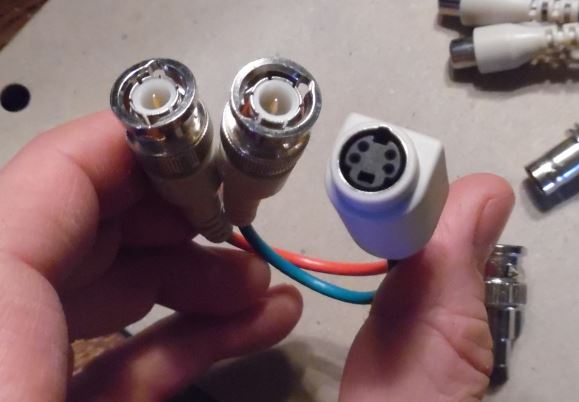
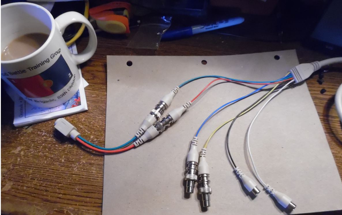
The Red cable is for "Y" Luminance Audio/Video Capture Connector
Capture cable connector ID
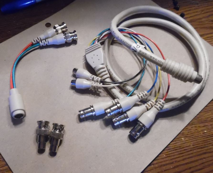 The BNC items at lower left are BNC to
RCA adapters. They go on the Blue and Yellow.
S-VHS Cable
  Connect a Composite Video Adapter (if
phono-to-BNC plug conversion is necessary) and the
video device's cable to the red connector on the
Capture Cable
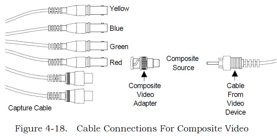 To do audio capture, continue with the section, "Connecting The Audio Capture Source." If you are not going to do audio capture, continue with the "Power On" section. S-Video Format 1. Connect red and green connectors on Capture Cable to corresponding color-coded S-Video Adapter (Y=red, C=green) supplied with Capture Module, as shown in Figure 4-19. 2. Connect video device cable's 4-pin DIN connector to S-Video Adapter's 4-pin DIN connector.. 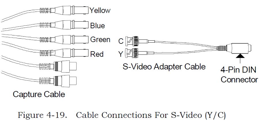 To do audio capture, continue with the section, "Connecting The Audio Capture Source." If you are not going to do audio capture, continue with the "Power On" section. RGB Composite Sync Format 1. Connect red, green, blue, and sync connectors on Capture Cable (sync=yellow) to corresponding color-coded connectors on video device, as shown in Figure 4-20. 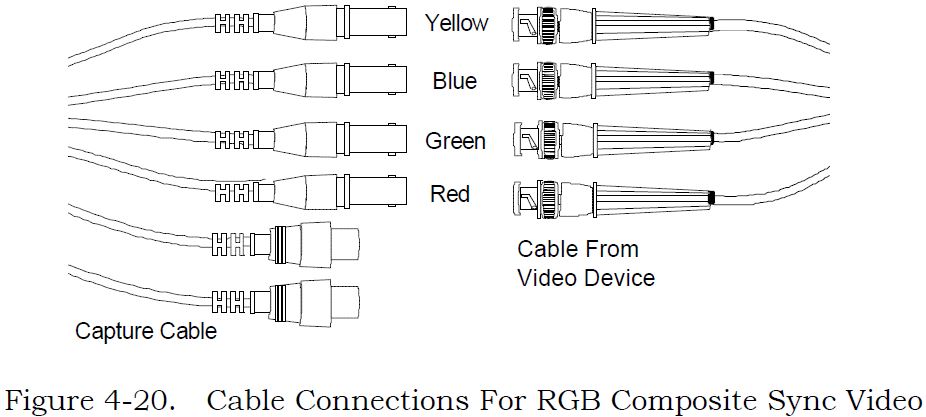 To do audio capture, continue with the section, "Connecting The Audio Capture Source." If you are not going to do audio capture, continue with the "Power On" section. RGB Sync On Green Format 1. Connect red, green, and blue connectors on Capture Cable to corresponding color-coded connectors on video device, as shown in Figure 4-21. 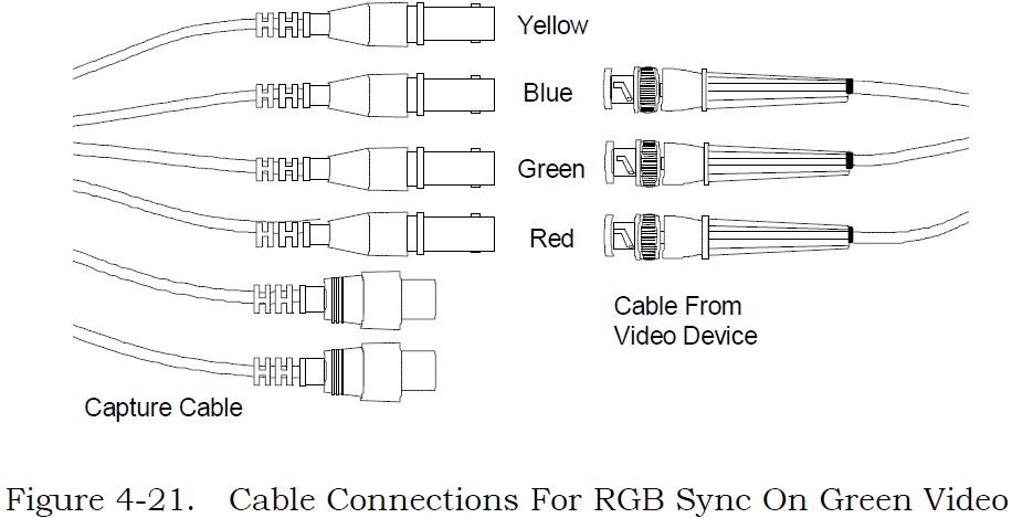 To do audio capture, continue with the section, "Connecting The Audio Capture Source." If you are not going to do audio capture, continue with the "Power On" section. Connecting The Audio Capture Source This procedure describes how to connect the audio capture source to your computer. 1. Locate audio device cable. 2. Connect cable to audio device. Refer to manufacturer's instructions. 3. ID left- and right-output channels on device's cable. Refer to manufacturer's instructions. 4. Connect audio device's left- and right-channel phono ("RCA") connectors to Capture Cable connectors (black=left, white=right), as shown in Figure 4-22. NOTE: If you have a mono device, you may need to purchase a Y-adapter cable. 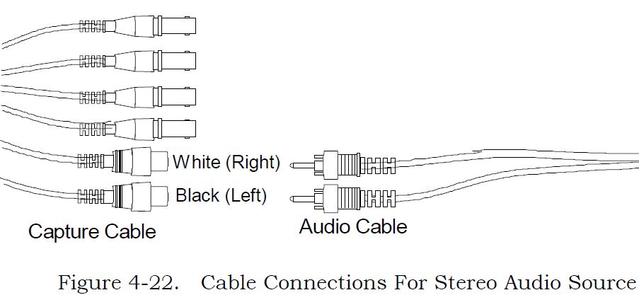 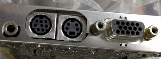 Capture
Connector Female Receptacle Pinout
Capture Cable Mini-DIN Male Plug Pinout 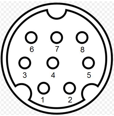
NOTE: I swept the pins, Pin 1 (Yellow) and Pin 2 (Blue) are correct (as of 16 Nov 2017). Any previous diagram of mine or IBM / Intel of the AM2 Mini-DIN 8 port may be wrong. All BNC shells are connected to Video Ground (Pin 4) The RCA plug shells for Audio Right and Left are connected to Pin 8. Audio Source Device
Levels: Audio Signal output connector The Audio Signal output connector is a 3.5mm standard stereo jack output connector. An amplifier, or active speakers can be attached to the AM2. The input impedance of the headphones or speakers should be at least 600 Ohms to match the output impedance. Use of a lower impedance devices may cause a POST error and a reduction in audio quality. If you are going to use sound, a stereo amplifier or self-amplified stereo device that can accept standard LINE-level audio output (0-2.0 Vp-p.) from the Delivery Board. The audio device must have an input impedance level of approximately 10K Ohms or greater. Headphones are generally low-impedance devices. To use headphones, plug them into an audio amplifier rather than directly into the Delivery Board socket. AM2 to
ACPA Audio Cable Some current thoughts... (the text in image is wrong!) AM2 audio output to ACPA Line Input - this cable works. ACPA Line Out to AM2 - use stereo mini-plug to two (2) RCA plugs, which then plug into the matching Black and White AM2 Capture cable audio jacks. Power Usage When configuring a PS/2 System with AM2, it may be necessary to limit the utilization of the system expansion slots to avoid the possibility of overloading the 12 volt power supplies. If the AM2 is being installed with the AM2 Capture Option then, besides the slot for the AM2, it is necessary to have a minimum of either: One empty expansion slot, or one slot occupied by a card not requiring +12 Vdc or -12 Vdc power. As a guide, it may be assumed that option cards providing networking or communication support are likely to require +12Vdc or -12Vdc power. ActionMedia II Board Power Requirements
Is anyone successfully using the ActionMedia II board to improve the performance of Video for Windows and as a capture device. It looks to me from the Microsoft documentation that I will need INDEO drivers. I have the MCI and other Windows drivers for AM2. Kevin Laux replied: First of
all, you must have AM2MCI\BIN in your PATH. Then
you must have a particular microcode file in this
directory that Video for Windows looks for in order to
enable the hardware assist. If you don't have the
microcode file, which is KE080201.BIN (I think; maybe
it's KE080205.BIN), you must get the files from Intel in
Princeton, NJ (609-936-7611 is the Customer Support
number - leave a message and they'll call you back). Once you
have the appropriate key microcode file, run the drivers
applet from the control panel. Choose Add, then
Add updated or unlisted driver. Insert the Drivers
diskette for Video for Windows and indicate what floppy
drive to the Add driver dialog (such as A:\). Next
a list of drivers will be displayed. Choose the
INDEO driver. You are reinstalling this
driver. If it has already been installed, you will
be prompted whether to replace it or not. Choose
New. The driver will be reinstalled. You
should then see a Message Box saying that the AM2MCI
software has been detected and has been updated. I
think you should also see the dialog box I described
above concerning the Hardware first, the Software. Once, this
is complete, you'll be ready to play and capture AVI
files with AM II hardware assist. Note that you
only get the assist on AVI files that are INDEO
files. Actually they are RTV 2.1 files in an AVI
wrapper. Lastly, this stuff is NOT documented anywhere that I know of (well, it is now that I've done this post :-)). Oh, and finally, if you don't have the AM2MCI software, you can call Asymetrix and get into the Beta program - the latest release is Beta 3. The phone number is 206-637-1660. ; Has anyone been able to use the IBM/INTEL ActionMedia 2 card with a laser disc player? Specifically, I want to use my PS/2 DV M57 486SLC2 to operate a Pioneer LD-V4400 player. IBM's multimedia group in Atlanta says I can't do it ... that I would an M-motion card to do what I want. I'm not sure I believe them. Suggestions as to software which can do what I want are greatly appreciated. George Mulford You need the capture option on the ActionMediaII in order to do video overlay. Now...maybe this is what Atlanta was saying: there is no MCI support for the overlay capability of the ActionMediaII. You have to link the AVK functions. Here I get fuzzy: there exists ToolBook code to do this, but it was only available in the "DVI ToolBook" that was in beta test for a bit and has now been withdrawn? Have I got this right? Is anybody bossing the ActionMediaII from ToolBook without using the (now black-market) beta DVI ToolBook? Digital Video Arts has operating system support software for Windows 3.1 for the AM 2 card. Called the NewWorld Operating Environment, it provides indeo acceleration, WAV driver support, digital video MCI device driver support, AVI and AVS file support and more. Several utilities are included for capture and conversion of movies and still images. Their phone number is (215) 586-7920. >>We've purchased an IBM Action Media II board a
while ago, and we've captured some videos in AVSS format
with it. Now that MMPM/2 is available, it would be nice
to play these videos without having the board installed.
Since AVSS seems not to be supported directly by MMPM/2,
the AVSS files probably need to be converted to AVI
format. Does anybody know about a converter for doing
that or has experience in using AVSS files with MMPM/2?
Well, having done a few....you first of all need to capture using RTV 2.1, not 2.0. It will take the audio out of the AVS file, an save it as a Wave file, to be integrated with the AVI file. But this utility is SLOW! It runs at 1 frame per second...even on a DX2/66 M77 machine! There is
another utility called "SPLICE". It did faster
conversions...but again, it had to be RTV 2.1 captures.
The New Version of Splice doesn't support AVS/DVI, so it
is kinda useless. Automatic configuration problem with ActionMedia/2 After an Automatic Configuration, the drivers for the ActionMedia/2 will claim that the adapter is not present, or is not functional (No video). The current automatic configuration algorithm selects the adapter configuration address option that occupies the smallest amount of space in the "adapter ROM area." For OS/2 or Windows, this may not be adequate. These address options are the same choices displayed during the manual "Change Configuration" function. This will select "NO SPACE USED (DISABLED)" for the ActionMedia/2 ROM space. Use the RefDisk (System Partition) "View Configuration, Change configuration" function, to manually configure the ActionMedia/2 ROM address to a other than 'DISABLED'. NOTE: Neither the Intel DS2 or the IBM AM2 ADFs have any "Disabled" for "POST Prom Address Range" / "Adapter Memory Location". My SWAG is that this really refers to IBM's "Extended Memory Window", which DOES have "Disabled". Intel's "VRAM Window Size and Starting Address" lacks any "Disabled". Intel DS2 and IBM AM2 ADF Oddities Perhaps one could have a easier install of an AM2 by editing the "IBM ActionMedia (TM) II Display Adapter/A" ADF. Either remove this line from "Extended Memory Window" entirely or comment it out with a ":" Choice "Disabled" POS[1]=XXXXXX1Xb POS[0]=XXXX111Xb Intel DS2 Adapter -- 12 July 1991 "VRAM Window Size and Starting Address" 8K, 32K, no "Disabled" IBM ActionMedia (TM) II Display Adapter/A "Extended Memory Window" 8K, 32K, "Disabled" exists False 10906x6 Error Lorenzo Mollicone was in the AM2 mines, when he got error code "1090636" a long beep, two short beeps, and OS/2 complained that the ActionMedia adapter was not found 109 - AM2 06 - 2-digit test category/subsystem code (FIFO Register test failed) 3 - Slot 3 (AVE connector) (9576 system) 6 - nature of failure or portion of test that failed 06x6 read EMS [0xffffc] (PAR0-PAR3) - FIFO Register test failed, indicating problem with memory access mechanism. Replace Delivery Board. So he replaced the board. Blammo, 1090636 again... After he got the System Programs to run (had to hold a key down after cold boot to force System Programs to come up), he found out that the Extended Memory Window was disabled. If you read the Automatic Configuration Problem above, you will understand that the autoconfig chose to disable the Extended Memory Window, which IS needed by OS/2 and Windows... Quote: "The OS/2 and Windows drivers for this adapter require an 8K window to operate. Some other drivers may require a 32K window" Can't read Extended Memory with no window... thanks, Captain Obvious! Now we have a no foolin' reason why you need to set the extended memory window... Once Lorenzo set an Extended Memory Window in System Programs (he chose 32KB in size) the beeps and error code disappeared and he was able to play the demo under OS/2. Solution: Do NOT allow the System Programs to auto configure an AM2. It just might set the Extended Memory Window to "Disabled" and you will spend an hour chasing a non-existent hardware problem! ActionMedia2 Error Codes If a hardware failure occurs, an error beginning with "0109" is displayed. The format is: 0109EESN 0109 Identifies the ActionMedia II board EE 2-digit test category/subsystem code S 1-digit slot number (1 to 8) (S is "0" in list, easier to read) N 1-digit nature of failure or portion of test that failed. Example: 01090270 (Installed in Slot 7 of a Model 95) 0109 - ActionMedia II board 02 - Delivery Board base I/O address and POST address are not the same 7 - Slot 7 (AVE connector) 0 - MCA Slot # not found NOTE: AM2 means Delivery Board (base adapter), CS means Capture Module.
AdapterID EFDC IBM ActionMedia II Display Adapter/A Adapter I/O Addressing
Extended Memory Window
NOTE: Intel DS2 ADF
"VRAM Window Size and Starting Address" lacks
"Disabled". Remove the line Choice
"Disabled" POS[1]=XXXXXX1Xb
POS[0]=XXXX111Xb or use a ":" to remark the
line out. Capture Option Interrupt Level
Video Interrupt Level
Audio Interrupt Level
Adapter Memory Location
|
 Analog
 keying. Need RGB Overlay Cable
Analog
Analog keying. Need RGB Overlay Cable