| Home |
| IMPORTANT: | The following is specific to the IBM 5150 (IBM PC), fitted with an IBM BIOS ROM. |
| Certain portions will not be applicable to clones that were made of the IBM 5150. |
| Error / Symptom | Description |
|---|---|
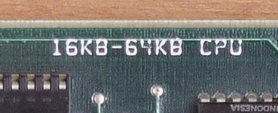
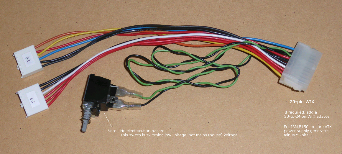
| [ Nothing ] | Even after two minutes, nothing on-screen, no beep/beeps were heard from the speaker, and no attempt was made to access the A: drive. It appears (repeat: appears) that the motherboard is dead. Understandably, this symptom has many causes. First, verify that you are not trying to power a 16KB-64KB version of the 5150 motherboard using an ATX power supply (with adapter) that does not generate -5V. See note 5. I suggest that you try the Minimum Diagnostic Configuration procedure at here. Also, consider the use of a diagnostic ROM in motherboard ROM socket U33 (i.e. in place of the IBM BIOS ROM): • Ruud's diagnostic ROM • Supersoft/Landmark diagnostic ROM If those ROM's do not show a problem, then see note 6 below. |
| Flashing cursor displayed on-screen, nothing else (no beeps, nothing), even after two minutes. | Some known causes: • I have seen this behaviour on an IBM 5150 that has faulty RAM refresh circuitry - see here. • An IBM 5161 expansion chassis is attached, one that contains an 'IBM Fixed Disk Adapter', and the switches on the extender card in the 5150 are set to 0011 ( [1=off][2=off][3=on][4=on]). Unknown cause. A workaround is to set the switches to 0100. |
At power on, you see the flashing cursor as expected. Later, the floppy drive's LED and spindle motor turn on, but never turn off. No futher progress. |
Some known causes: • The motherboard BIOS is the 10/19/81 one, and one or more of the Cassette BASIC ROM chips on the motherboard (U29 through U32) has failed. • If you were attempting to boot DOS, see here. |
At power on, the power-on self test (POST) does not access drive A: at all. There are no error messages on-screen, and the computer boots to Cassette BASIC (or hard drive). |
A known cause: Switch 1 in the motherboard's switch block SW1 is in the ON position. |
At power on, you can boot to floppy, but not to Cassette BASIC. |
If re-seating the Cassette BASIC ROM's (U29 through U32) does not remove the symptom, boot from disk, then run the 5150ROMS tool. 5150ROMS, available at here, is expected to show the problem cause. |
"Starting MS-DOS..." is displayed on-screen and then there is no further progress. The floppy drive's LED is on continuously. |
The IBM BIOS on the IBM 5150 motherboard does not generate this error. This message is produced by later versions of DOS, to inform you that DOS has started loading. See here for some possibilities as to why DOS 'fell over' whilst starting. |
| "Disk Boot failure" is displayed on-screen and then there is no further progress. | The IBM BIOS on the IBM 5150 motherboard does not generate this error. As an example, it is seen in the boot sector of IBM DOS 3.3 See here for some possible causes. |
| Continuous beep (tone) | The POST does not output a continuous beep (tone). Known causes: • Faulty motherboard. • Faulty expansion card (faulty in a way that interferes with motherboard operation). • Faulty power supply. Note: Do not assume that a power supply is good because it is generating a POWER GOOD signal. Note: At here is my hypothesis. |
| 1 long beep then 1 short beep | Two causes: • The POST's test of the motherboard's 8259 chip (includes supporting chips) failed. • The POST's test of the motherboard's 8253 chip (includes supporting chips) failed. ( If the motherboard BIOS is the 04/24/81 one, do not confuse this symptom with the next listed symptom following. ) NOTE: For detail, see actions '8259 TEST' and 'TEST/SET TIMER 0' at here. |
| 1 long beep then 1 short beep, then about 15 seconds later, 1 short beep |
Only the 04/24/81 dated motherboard BIOS generates this error. Indicates failure of one or more of the BASIC ROM chips on the motherboard (U29, U30, U31 and U32). |
| 1 long beep then 2 short beeps | Some causes: • 5150 motherboard - Configured via SW1 for an MDA video card, but either the POST cannot find an MDA video card to initialise, or the MDA card is faulty. • 5150 motherboard - Configured via SW1 for an CGA video card, but either the POST cannot find an CGA video card to initialise, or the CGA card is faulty. • A video card with a BIOS expansion ROM did a self test and found a problem with itself. • A bug in the 5150's POST - see description of 'C800 ROM' below. |
| 1 long beep then 3 short beeps | The BIOS expansion ROM on an IBM EGA card is known to generate this if it discovers that the card has faulty RAM. |
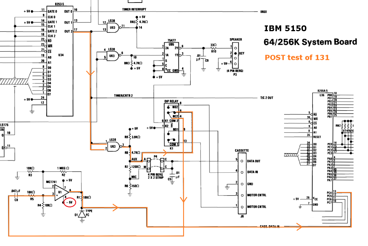
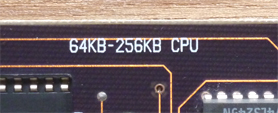
| 131 displayed on-screen | Failure of cassette port wrap-around (loopback) test. Wrap-around diagram at here. Some possible 131 causes: • 5150 motherboard of type 64KB-256KB is not receiving minus 5 volts (chip U1 on the 5150 motherboard requires minus 5 volts). - Try reseating plug P9 from power supply, in case of bad connection. - Perhaps in use is an ATX power supply (via adapter) that does not have a minus 5 volts output. • Faulty motherboard - see note 3 for more information. |
| 201 displayed on-screen (xxxx 201) |
RAM related error. For the 5150, the 201 will be prefixed by a 2 bytes (e.g. "0410 201"). For the 5150, after the 201 error is displayed, it is normal for the screen to clear, then either 'PARITY CHECK 1' or 'PARITY CHECK 2' appear. Some possible 201 causes: • 5150 motherboard - failure of a RAM chip. (And there may be more than one failure.) • 5150 motherboard - RAM chip has poor connection to the motherboard. • 5150 motherboard - failure of the circuitry that supports RAM. • 5150 motherboard - incorrect switch settings of SW1/SW2. • 5150 motherboard - 10/27/82 BIOS fitted and less than 4 banks of RAM fitted (that BIOS requires 4 banks, together with SW1/SW2 set accordingly for that). • 5150 motherboard - incorrect type of RAM chip fitted. • 5150 motherboard - printed circuit board (PCB) problem (bad solder joint, damaged traces, damaged IC socket). • RAM expansion card - failure of its RAM or circuitry. • RAM expansion card - incorrect switch settings on card. Note: Faulty RAM refresh circuitry may not result in a 201 error on an IBM 5150. See here. More information on IBM 5150 RAM at here. |
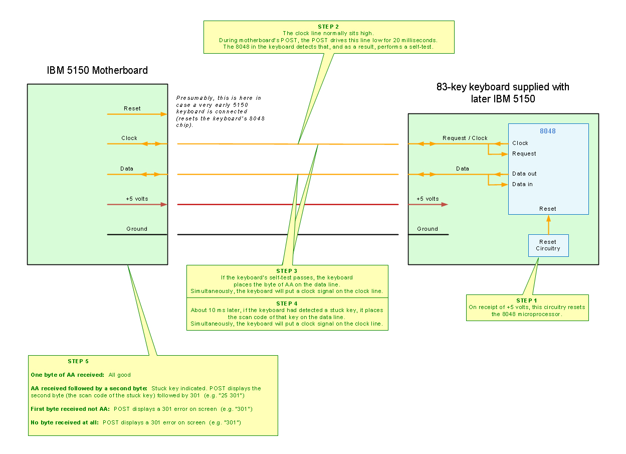
| 301 displayed on-screen (301) (xx 301) |
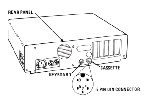
Keyboard related error. If the "301" is preceeded by a byte, e.g. "23 301", then the keyboard's self test is indicating to the POST that a key is 'stuck' down. The byte indicates which key (see here). If the "301" is not preceeded by a byte, then it's a general keyboard error. Possible causes: • No keyboard attached. • Keyboard accidentally attached to cassette connector instead of keyboard connector. • AT class keyboard attached. That will not work. A PC/XT class keyboard is required. • Faulty keyboard - broken wire in cable. • Faulty keyboard - wire loose in connector. • Faulty keyboard - chip failure. • Faulty motherboard - bad solder joint on DIN connector for keyboard. • Faulty motherboard - some cases of faulty keyboard circuitry. A related diagram is at here. |
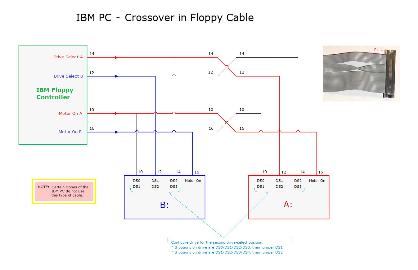
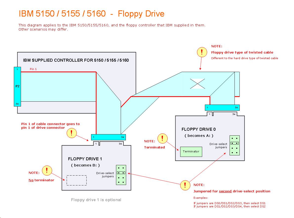
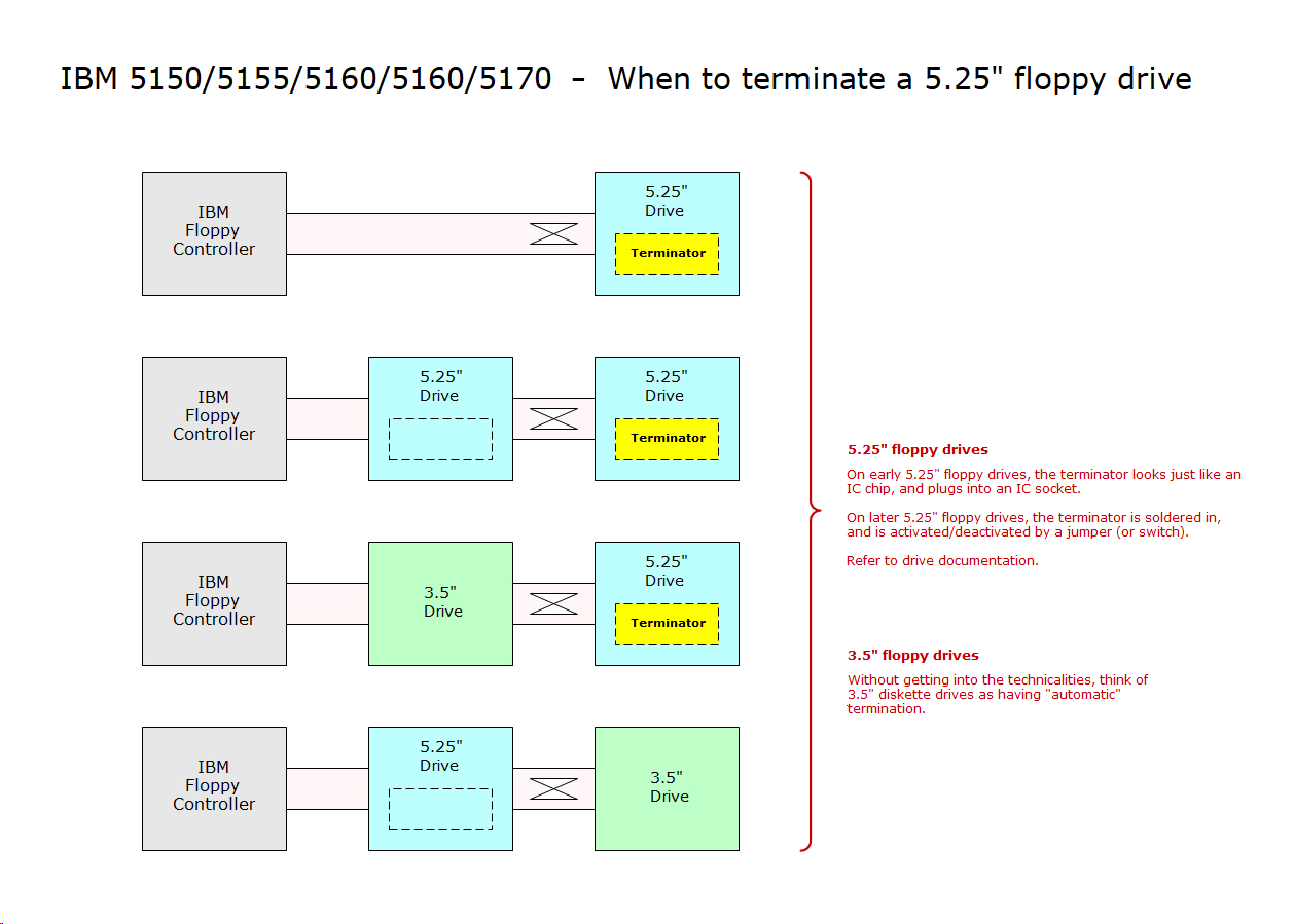
| 601 displayed on-screen | Test of physical floppy drive 0 failed. (DOS presents this to user as logical drive A:) Some possible 601 causes: • Floppy controller card - faulty. • Floppy controller card - dirty edge connectors. • Floppy controller card - not seated correctly in motherboard's expansion slot. • Motherboard - edge connector contacts in expansion slot are dirty/damaged. (Try a different slot.) • Floppy cable - faulty. • Floppy cable - not the correct type for a 5150 - see here. • Floppy cable - not fitted correctly - see here. • Floppy drive - faulty. • Floppy drive - drive select jumper not set properly - see here. • Floppy drive - not compatible. • Floppy drive - compatible, but not configured correctly for a 5150. • Floppy drive - some cases of improper termination. |
| 1701 displayed on-screen | This error is not generated by the motherboard's POST, but by the initialisation code within a BIOS expansion ROM residing on an XT-class hard disk controller. The maker of the particular XT-class hard disk controller decides in which situations they have their controller display the "1701" error. 1701 is typically a very high level error, indicating a problem with the hard drive system (system = controller + cables + drive + configuration + power). So, lots of possible causes. See here for some ideas. |
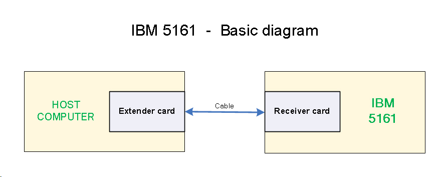
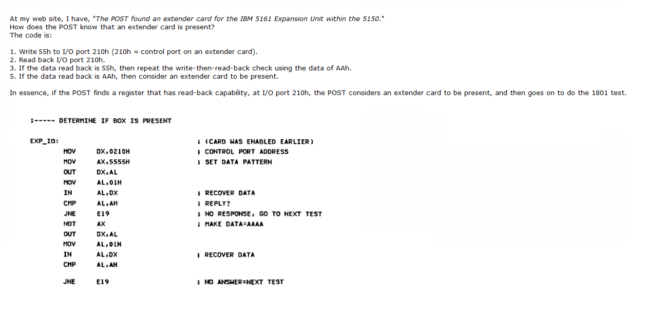
| 1801 displayed on-screen | Related diagram at here. The POST found an extender card for the IBM 5161 Expansion Unit within the 5150. Because of that, the POST made an assumption that a 5161 Expansion Unit is connected to the card. The POST attempted to communicate with the 5161 and because that communication failed, the POST displayed 1801. Some possible 1801 causes: • 5161 Expansion Unit - not connected to the extender card in the host computer (e.g. missing cable) (e.g. loosely connected cable). • 5161 Expansion Unit - not powered on (should to be powered on before the host computer is). • 5161 Expansion Unit - faulty system board (backplane). • 5161 Expansion Unit - power supply - faulty. • 5161 Expansion Unit - power supply - has shut down due to a fault elsewhere in the 5161. • 5161 Expansion Unit - power supply - has shut down due to inadequate loading. • Cable - faulty. • Cable - oxide build-up on the contacts within the two connectors. • Extender card - faulty. • Extender card - not seated correctly in host computer's ISA expansion slot, or poor connection (e.g. dirty contacts). • Extender card - oxide build-up on the contacts within the cable connector. • Receiver card (within 5161) - wrong type. See here for a photo of the correct type. • Receiver card (within 5161) - faulty. • Receiver card (within 5161) - not seated correctly in 5161's ISA expansion slot, or poor connection (e.g. dirty contacts). • Receiver card (within 5161) - oxide build-up on the contacts within the cable connector. Additional: It is known that an 1801 error can sometimes be incorrectly triggered if an accelerator card is fitted. See here. |
| C800 ROM displayed on-screen | An expansion card has a BIOS expansion ROM addressed at C8000, and that ROM is partially faulty or has corrupt contents. C8000 is commonly used by XT-class hard disk controllers. Because of a bug in the 5150's POST, you will never see this error. Instead, you hear the '1 long beep then 2 short beeps' error, leading you to believe that a video problem exists. |
| CA00 ROM displayed on-screen | An expansion card has a BIOS expansion ROM addressed at CA000, and that ROM is partially faulty, or has corrupt contents, or has poor connection to the card. CA000 is commonly used by third-party floppy controllers (those that have a BIOS expansion ROM). |
| D000 ROM displayed on-screen | An expansion card has a BIOS expansion ROM addressed at D0000, and that ROM is partially faulty, or has corrupt contents, or has poor connection to the card. |
| F600 ROM displayed on-screen | Motherboard ROM chip U29 (contains part of Cassette BASIC) is missing or faulty or corrupt, or has poor connection to the motherboard. INFO: Only the 10/27/82 BIOS generates this error. |
| F800 ROM displayed on-screen | Motherboard ROM chip U30 (contains part of Cassette BASIC) is missing or faulty or corrupt, or has poor connection to the motherboard. INFO: Only the 10/27/82 BIOS generates this error. |
| FA00 ROM displayed on-screen | Motherboard ROM chip U31 (contains part of Cassette BASIC) is missing or faulty or corrupt, or has poor connection to the motherboard. INFO: Only the 10/27/82 BIOS generates this error. |
| FC00 ROM displayed on-screen | Motherboard ROM chip U32 (contains part of Cassette BASIC) is missing or faulty or corrupt, or has poor connection to the motherboard. INFO: Only the 10/27/82 BIOS generates this error. |
| PARITY CHECK displayed on-screen | Intermittent and unlike below, there is no '1' nor '2' following 'PARITY CHECK'. A computer virus named Parity_Boot is known to display this - see here. (The IBM BIOS in an IBM 5150 always displays a 1 or a 2 after PARITY CHECK.) |
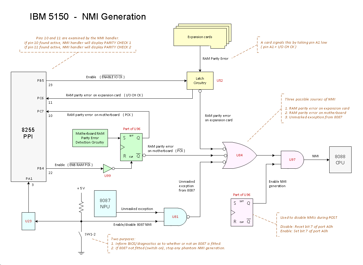
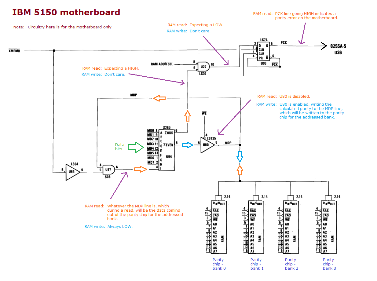
| PARITY CHECK 1 displayed on-screen | A parity error occurred when an address in motherboard RAM was read. (The '1' indicates motherboard.) Related diagram at here. Strickly speaking, this is not a POST error. Not only may it be seen near the very end of the POST (at the time when NMI's get enabled), it may also be seen any time later (when motherboard RAM is being read). SITUATION #1 - NEAR END OF POST A parity error occured during the POST's test of motherboard RAM. That is registered (via motherboard chip U96), but because NMI's are disabled during the RAM test (via motherboard chip U97), PARITY CHECK 1 is not seen at that time. Later, near the end of the POST, NMI's get enabled, and at that instant, an NMI is generated, and PARITY CHECK 1 then generated/seen. SITUATION #2 - LATER Seen sometime after the POST has completed, e.g. when Cassette BASIC or DOS or a DOS program/driver is running. Seen at the the time when a parity error occurs as a result of an address in motherboard RAM being read. Most likely causes: • 5150 motherboard - Some cases of incorrect switch settings. See note 2. • 5150 motherboard - RAM chip failure. • 5150 motherboard - A RAM chip (possibly multiple) has a poor connection to the motherboard. Some other possible causes: • 5150 motherboard - Bad RAM refresh circuitry. • 5150 motherboard - Bad parity generation circuitry. • 5150 motherboard - Bad filter capacitor/s close to the RAM chips. (Of those, suspect the tantalum type ones before the ceramic type ones.) • In an early IBM 5150, 'PARITY CHECK 1' is sometimes seen when there is not enough RAM for DOS. See here for more information. • If intermittent, see note 1. |
| PARITY CHECK 2 displayed on-screen | A parity error occurred when an address in expansion card hosted RAM was read. (The '2' indicates expansion card [ISA card].) Related diagram at here. Strickly speaking, this is not a POST error. Not only may it be seen near the very end of the POST (at the time when NMI's get enabled), it may also be seen any time later (when expansion card hosted RAM is being read). SITUATION #1 - NEAR END OF POST A parity error occured during the POST's test of RAM on an expansion card. That is registered (via motherboard chip U52), but because NMI's are disabled during the RAM test (via motherboard chip U97), PARITY CHECK 2 is not seen at that time. Later, near the end of the POST, NMI's get enabled, and at that instant, an NMI is generated, and PARITY CHECK 2 then generated/seen. SITUATION #2 - LATER Seen sometime after the POST has completed, e.g. when Cassette BASIC or DOS or a DOS program/driver is running. Seen at the the time when a parity error occurs when an address in expansion card RAM being read. Most likely causes: • Expansion card - RAM chip failure. • Expansion card - A RAM chip (possibly multiple) has a poor connection to the card. Some other possible causes: • 5150 motherboard - Bad RAM refresh circuitry on motherboard - Example recorded at here. • Expansion card - Bad RAM refresh circuitry on card. • Expansion card - Bad parity generation circuitry on card. • Expansion card - Bad filter capacitor/s close to the card's RAM chips. (Of those, suspect the tantalum type ones before the ceramic type ones.) • Expansion card - RAM placed above the 640K address, and that RAM was not written to (to appropriately set/reset the parity bit) before it was read. • If intermittent, a computer virus is known to display 'PARITY CHECK 2' - see here. • If intermittent, see also note 1. |
| Note 1 | If intermittent: • Verify that the mains AC power (house power) fed to the computer is within specification and stable. Someone on the Vintage Computer Forums indicated that the cause of their intermittent PARITY CHECK errors was their air conditioner (when the compressor kicked in/out). • The computer's power supply may be the cause. • Bad RAM chip/s may be the cause. • Bad RAM support circuitry may be the cause. (One example: bad filter capacitor/s close to the RAM chips.) • In case of poor electrical contact, try re-seating the RAM chips in their sockets. |
| Note 2 | I.e. Settings that result in the POST/DOS believing that the amount of RAM is less than fitted, and that can lead to the situation described at here. |
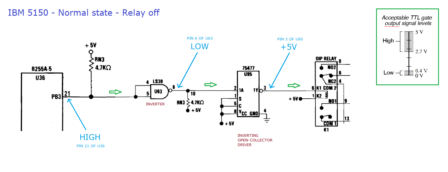
| Note 3 | Assuming a faulty motherboard, a problem somewhere in the orange path shown at here. Perform the following checks in the order shown. First check: Use a multimeter to confirm that -5V is reaching pin 4 of motherboard chip U1. Next check: If pins pins 1 and 3 of the motherboard's cassette DIN connector are closed circuit (zero or low ohms) when the motherboard is unpowered, then motherboard relay K1 (cassette relay) is at fault. In which case, try lightly tapping the relay with the handle of a screwdriver. Next check: If pins pins 1 and 3 of the motherboard's cassette DIN connector are open circuit (infinite ohms) when the motherboard is unpowered, AND closed circuit (zero or low ohms) when the motherboard is powered, then a motherboard fault has relay K1 (cassette relay) turned on all the time. In which case, use the diagram at here to work out the faulty component. Next: Assuming a faulty motherboard, then because the above checks did not reveal the problem, we know that the problem cause is somewhere in the orange path shown at here, but not the relay nor the circuitry that turns the relay off and on. |
| Note 4 | Why isn't the POST comprehensive ? - There is not much space in the motherboard ROM for the POST, so the POST is small and crude. - The POST has to execute in a short amount of time - users do not want to wait 30 minutes or more after turning on the computer. - The POST is not going to do things like: * Example: Get you to press every key on the keyboard to see if all keys register. * Example: Put a known-good formatted floppy in the floppy drive then do a read/write test of every track, in order to verify that read/writes are working, heads are stepping properly, good alignment. The POST being small and crude, is very limited in what it can do. It is why diagnostic disks, diagnostic ROM's, diagnostic programs exist, and even they cannot detect all problems. |
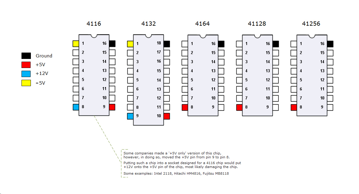
| Note 5 | The RAM chips on the 16KB-64KB version of IBM 5150 motherboard are type 4116. 4116 chips are powered by +5V, -5V, and +12V. If any of those voltages are not reaching the 4116 chips, the POST test of the first 16 KB of RAM will fail, then the POST will simply halt (providing no audible nor visual indication) - the 16KB-64KB motherboard will appear to be dead. |
| Note 6 | If neither 'Ruuds diagnostic ROM' (RDR) nor the 'Supersoft/Landmark diagnostic ROM' (SLDR) show any problem, then maybe the IBM BIOS ROM chip is faulty. But it is known that RDR and SLDR do not test everything. And SLDR does not check for RAM addressing problems, but RDR and the IBM BIOS ROM do (with the IBM BIOS ROM not showing anything on-screen, nor beeping the speaker). For the IBM 5150, RDR is very much preferred over SLDR. |