|
Ultimedia Module Ultimedia Module PCB Ultimedia Module PCB, Top Ultimedia Module PCB, Bottom DIY IBM Ultimedia-to-CT 5330 by pleonard (original post on VOGONS) 77 Case, Rear Remove Cover Ultimedia Adapter (to another page) 76/77 Model Codes 76/77 i/s Model Codes Lacuna vs. Bermuda Upgrading Planars Devil's in the Details 77 Bermuda Riser 9577 Multimedia Model Features 9577S Multimedia Model Features 77 5.25" Drive Bay Guides Guide FRUs Remove Guides Original 5.25" Drive Rail 5.25" 77 Drive Rail Hack PCMCIA Adapter Mounting 9577 Drive Slide 9577 Air Baffle for Fixed Disk Drive Bay 4C Air Baffle Pasteboard Hack SCSI Controller Sets HD as 6,1 Instead of 6,0
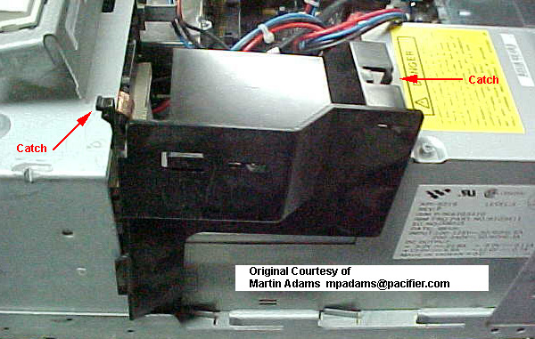
77 Case, Front (40, 57 similar) Multimedia Model shown 
77 Multimedia Module (Image and some comments from William
R. Walsh) Original HERE
Both standard and MM control panels have a
speaker. Only the MM control panel has Microphone and
Headphone jacks (1/4" stereo jacks). The MM speaker
(behind the grille) is rated 1.5 watts / 8 ohms as
compared to 0.5 watts at 4 or 8 ohms. The shape is an
oval cone set into a square frame. The standard control panel lack the microphone, headphone and volume features. 41G3929 Control Assembly: - With Volume Control (Power Switch, Cable, and Speaker) Multimedia Module PCB (outline and comments by William R.
Walsh) original HERE
U2 - Philips TDA1015 1-4 watt self contained power amplifier (datasheet) MultiMedia
Module PCB, Top
FRU 41G3929 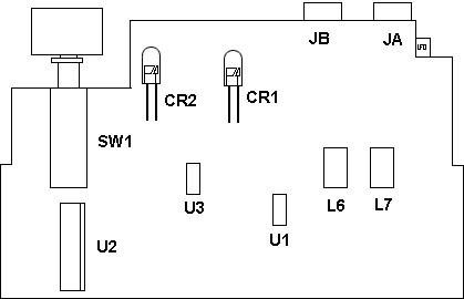
U1,3 LM837M Low Noise Quad Operational Amplifier Datasheet U2 Philips TDA1015 1-4 watt self contained power amplifier Datasheet MultiMedia Module PCB, Bottom FRU 41G3929 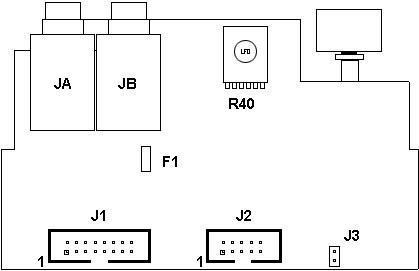
96F7762 Cable (Control Assembly to System Board) DIY IBM Ultimedia-to-CT 5330 by pleonard (original post on VOGONS) Those of us (un)lucky enough to have collected an Ultimedia PS/2 know that the audio features of this machine are a mix of good and bad: great front-panel amplified speaker with volume control and headphone/mic jacks, coupled to a terminally-unsupported audio card (M-ACPA or AudioVation, choose your MWAVE DSP poison). The question is: how to connect that great front-panel speaker up to a useful sound card? As you might expect, audio is connected through a proprietary 16-pin connector that plugs into IBM's own audio cards. A few 3rd-party boards (ChipChat among them) include this "Ultimedia Header", but Creative's own SoundBlaster Pro MCV (CT-5330) does not. Since the pinout has been documented by the PS/2 community.. [ed: actually by me...] 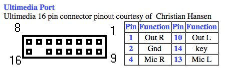 ...and since you can buy 2x8 dual row headers ...it should be relatively easy to solder up a R/L/Gnd cable from the line out jack on the back of the SoundBlaster Pro: [ed. pleonard connected Pins 1 (R), 2 (Gnd), and 10 (L).] 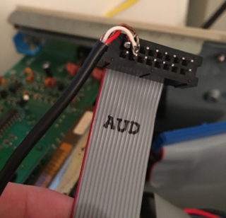 (believe it or not, those pins aren't shorted  ) )As you'd expect, best results are obtained by disabling the built-in amp on the SBPro. The result is very clean sound -- contemporary (1991) reviews of the Ultimedia mention how these machines' own sound hardware obviated the need for external speakers for most users. Best of all, you can completely uninstall the original DSP sound card. (Your sympathies for the original IBM sound card will dramatically decrease when you discover how many dozens of KB of RAM it requires to produce sound of any kind in DOS...!) Have front facing away Unscrew both thumbscrews "Slap" the top of the case forward using your palms along the sides of the case When the top of the case moves forward an inch and a
half, pull up.
9576 and 9577 Model Codes Dxx=Choice of OS Kxx=OS/2 2.1 Qxx=DOS/Windowze 3.1 1xx=MM (Ultimedia) xNx=DX2-66 (5v) xUx=SX-33 (5v) xxA=212MB SCSI xx6=104MB SCSI xxF=400MB SCSI 9577
Ultimedia Model Features 9576 and 9577 i/s Model Codes Thanks for showing the EASY way, Oloruin! Axx=Lacuna, On-board IDE, built-in S3 video 9577S Multimedia Model Features All the multimedia models include the following
features: Ed. I found NO MM 76 models. Upgrading planars You can upgrade any current PS/2 76/77 or PS/2 56/57 with the new PS/2 Planar Upgrade. You'll gain all the advantages of the new 76/77 i and s systems. Current 76/77 systems will perform up to 38% faster while keeping everything else intact. Devil's
in the Details The two broad classes of box designs that
led to the 9576 and 9577. Taller box: Of course, the 855X were 80386DX or 80386SLC, so they used a completely different system board. The 9576 and 9577 used the same system board (=Bermuda), one with SCSI built into the board (=Bermuda). The 9576i and 9577i (Lacuna system board) were made in two different clock speeds -- 25MHz and 33MHz. Their system board FRU part numbers were: 25MHz only: 95G9691 (not
streaming transfer capable) A 957Xs is only a 957Xi with a modified
Future Domain SCSI card added to one of the adapter
slots on the bus riser card, to handle internal/external
SCSI devices. Parts Comparison: 9576 Bus
adapter*
87F4833 9556 Bus
adapter*
79F7210 8556 Bus
adapter*
79F7210 9577i/s 5-slot bus riser
assembly 68G2709 9577 Bus
adapter riser card
87F4836 9557 Bus
adapter riser card
41G3877 8557 Bus
adapter riser type 1 85F0056
So you see, it is important to know both
the part number and clock speed limitation of the
Lacuna-type board, and to have the correct bus riser
card for the particular box/system board. In other
words, you cannot really upgrade a 957X to a 957Xi/s
without changing the riser card as well as the system
board! IBM 76 Security Cable Cover . Hmm, never seen one. MULTIMEDIA MODELS The pinout of the standard 9577 speaker/power switch module is 
Not supported o IBM PS/2 8514 Display Adapter/A (#4054, 1887972) o IBM PS/2 Micro Channel SCSI Adapter (#1005, 6451109) o IBM PS/2 Micro Channel SCSI Adapter with Cache (#1018, 6451110) o IBM Mwave WindSurfer-MCA Communication Adapter/A (#7058, 82G7058) The IBM 1GB AT Hard Disk Drive (#2543, 70G8512) is supported with the following limitation: If you experience problems configuring this drive as the "master" with any other fixed disk drive in your system, reconfigure this drive as the "slave" drive. Secured removable media via 2.88MB Electronic Eject
Diskette Drive (optional) 77 5.25" Drive Bay Guides  Post- Notches on the reverse that fit into the drive bay walls. Latch- Locks the guide onto the drive bay wall. Guide
FRUs To
remove Guides This was "fun". On this rail, the screw
hole marked "R" was the fixed hole, and it serves as the
reference point for the important surfaces. Note that
the center-to-center distance is 3.115". Measured that
from a drive. One hole is usually slotted so there can
be some variation between mounting screw locations on
drives. 5.25"
77 Drive Rail Hack PCMCIA Adapter mounting I finally got around to installing the PCMCIA adapter in my 77s. The trick- mount the adapter on a 76/77 floppy tray. (Adapter MUST be in the stamped metal bay PN 64F1270) Remove the rail guides on the dive support stucture in the 77. (Catches are on the inner end) swap the guides to the other side and push them onto the mounting studs. Now turn the tray/adapter upside down and push it into the rails. Note that the two card ejection buttons are now on the left side of the adapter. Just happens to be the exact height to perfectly fit the bezel. Fixed Disk Bay 4C Drive Slide 96F7775, 71G5706, 71G5708, 79F3300 
Seems this is a little long for OAL for it to fit into the Model 90's lower drive bay. 9577
Air Baffle for Fixed Disk Bay 4C FRU 92F0251 The older 8557 and 9557 used a grey colored baffle, same FRU. This was used in older systems with hot running drives in 4C. Modern 1" high drives should run cool enough without it, but if you want to run a 7,200RPM (or higher) drive in your 77, you MIGHT want to help cool it as much as possible. Pasteboard hack
PS/2 - 76/77 S Model Configures SCSI HD As 6,1 Symptom: The 9576 or 9577 system configures the harddisk with a SCSI ID of 6,1 instead of 6,0. A POST error of 1047000 107 may also occur. Problem Isolation Aids:
Fix: |