|
8555 Power 8555 Procomm Riser 189-076 PS/2 Model 55 SX and 80387SX Math Co-Processor (8555-031 and 8550-061) 189-089 IBM PS/2 Model 55 SX (8555-R31 and 8555-R61) 190-171 IBM PS/2 Model 55 LS (8555-LT0 and 8555-LE0) 191-077 IBM PS/2 Model 55 SX (8555-041 and 8555-081) and Memory Upgrade for 55 LS SHS15F2195 IBM PS/2 Model 55 SX HMS SHS15F2250 IBM PS/2 Model 55SX HMR Extract of 8555 from HMM Model 55 Technical Reference, 2d Ed (Oct 90) (Thanks to Peter Wendt) Model 55 Technical Reference, 1st Ed (Feb 89) Internet Archive Reworking the DS1287 / DS1387 RTC chip (Peter Wendt) Early Planar Late Planar Early Riser Newer Riser Late Riser IBM PS/2 Model 55SX Hangs at Start Up with Windows 3.1 Both of these planars and the three risers were sent to me by David Beem from New Mexico. ADF
Sections for Integrated Fixed Disk and Controller Early 8555SX Planar 
Early Mod. 55SX had a risercard connector with too long solder pins. If you applied pressure to the top of the case the pressure goes onto the riser card, which presses down the systemboard ... which makes contact with the grounded metal on lower chassis for some databus signal pins. [snip] (IIRC there was an ECA "IBM dealer confidential" on this topic) - the "dead cockroach" board with the many patch wires and the glued, silver-capped patch chip. Needs the almost bare riser card, does not work with the later ones (or: not always). Had various problems from which the non-functional pin to shut off the 386SX is the worst. Does not work with "clip-on" processor expansions. Fails with 8514/A + network cards. 305 ERROR CODE In The IBM PS2 Model 55SX From COMPUTERCRAFT This generally results from an easily replaced fuse on the motherboard, right near the Keyboard and mouse connectors. The fuse is in a holder. No soldering is required to remove it. The fuse is made by BEL FUSE - 5MF, 3 AMPS, 250 VOLTS [5MF(P) 3-R]. Radio Shack equivalent is part number 270-1054. It's also called a type GGS 5x20 mm fuse. An exact replacement from another source may be substituted. This fuse often goes when a serial mouse is used with a PS2 adapter. Only use a true PS2 style mouse in the 55SX. The keyboard or the mouse could also be bad. 160 POST Error A 160 POST error will be displayed if the Bus Adapter Card (FRU P/N27F4666) is not installed in an 8555. If the Bus Adapter is removed for problem determination, or not re-installed after replacing the system board, the system will not complete POST successfully. The Bus Adapter Card is required by the 8555 for system self-identification. 160 POST error may also be caused by a defective bus adapter. 168 POST ERROR ON 8555 If a 168 POST error code is displayed after replacing the system board in an 8555, verify that the correct system board is installed. If the correct system board is installed, a 168 error usually represents a Token Ring adapter problem. The 8555 LAN SYSTEM BOARD P/N 33F8159 is intended for use in special bid 55SX MEDIALESS* Workstations. If installed in an 8555 MODEL 031 OR 061, the machine will POST a 168 error and will not boot from drive A. * NOTE: 8555 "MEDIALESS" Models may be upgraded with diskette and fixed disk drive options. The model number should be used to determine the correct system board FRU. 8555 System Board FRU P/N 27F4667 Model 031 AND 061 (55SX). Bus Adapter, 55SXS FRU P/N 27F4666 57F3003 Model LT0 AND LE0 (55LS). Bus Adapter, 55LS FRU P/N 64F3732 33F8159 Model B00, C00, P00 (55SX MEDIALESS). 104XX ERRORS In a PS/2 55SX (Model 061 ONLY) H035587 If a 104XX error occurs in an 8555 Model 061, check for a power supply barcode label K1DLXXXXXXX (X = any number). If the bar code matches, replace the power supply (this power supply can also be identified by a plastic power supply fan grille). If the power supply does not match the above description, follow the normal problem determination procedure. IMPORTANT: This power supply should be replaced in 8555 Model 061's only. 201 POST Error On 8555 MEM Location H063320 If an 8555 displays a 201 POST error, verify that a SIMM has been installed in the connector closest to the edge of the system board, next to the power supply. If the memory is installed correctly, and the error remains, follow FRU isolation procedures in the hardware maintenance service pamphlet. 8555 System Board Damage And Related Handling H021594 Failure analysis of returned PS/2 8555 system boards has revealed that some boards have physical damage to the phase lock loop (PLL) SIP component. The PLL SIP is a small ceramic circuit board, mounted vertically on the system board. It is approximately one inch wide and 3/4 inch tall, and is soldered to the system board very close to the power supply cable connectors. The reported damage is a result of the PLL SIP being bent at its system board connectors. The PLL SIP is supposed to be mounted at a 90 degree angle to the system board. Its design will permit some connector bending (up to a 20 degree angle from its intended perpendicular mount). Once bent, however, the PLL SIP must not be straightened. *** IMPORTANT *** - On the replacement system board FRU, if the PLL SIP is bent toward the power supply connector, and interferes with plugging in the power supply cables, do not straighten the PLL SIP. Return the system board as new defective. - If bent away from the power supply connector, and if the system board operates, the system board should be considered good. Do not straighten the PLL SIP. Late 8555SX Planar 27F4667 / 57F1536 
- the revised 55SX board FRU 27F4667. Components slightly rearranged. Riser cards have more capacitors and / or the 74LS-something that fixes a problem with 8514/A-style cards. 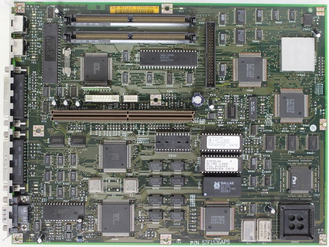
55LS "netcomputer" planar FRU 57F3003 / 84F6889  84F6897 BIOS Odd 84F6896 BIOS Even ZM64 (???) 63F7530 (???) >What
is
the unpopulated 28-pin DIP socket by the RTC? None of my
55 boards have it filled in. RIPL ROM if the network
board didn't have it?
24-pin - as you noted in your follow up posting. Peter says: It is for a 2K CMOS Ram extension chip (6116 or
something) that adds to the one in the Dallas RTC -
needed for some purpose on totally medialess 55SXs (no
FDD, no HD, only NIC). I think it is intended to hold
some system status / shutdown infos that are usually
written to disk. William Walsh: >
Also has anybody ever seen the resisters soldered on top
the IMGS171S-35, it's labeled as ZM2 on Louis's page.
On this machine they have soldered 6
resistors in connecting some of the pins on that chip.
I'm wondering if this is a custom job or something
IBM did??
It's something IBM did. I don't know what the exact
purpose is, but it circumvents problems that IBM
experienced with the RAMDAC. Model 30-286 planars may also
have this fix. David Beem: They are diodes. Only present for some plastic versions of the RAMDAC. The ceramic version was fine. Early
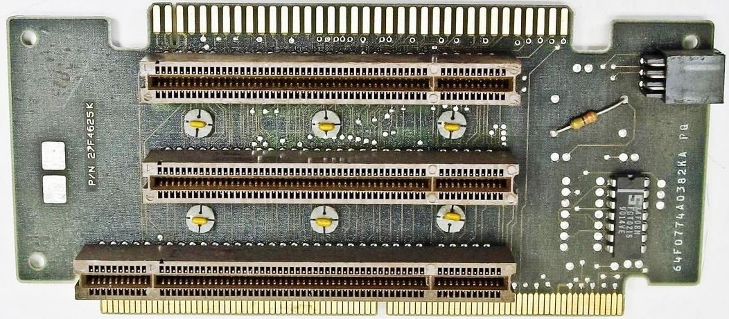
Riser P/N 27F4625 / 27F4630 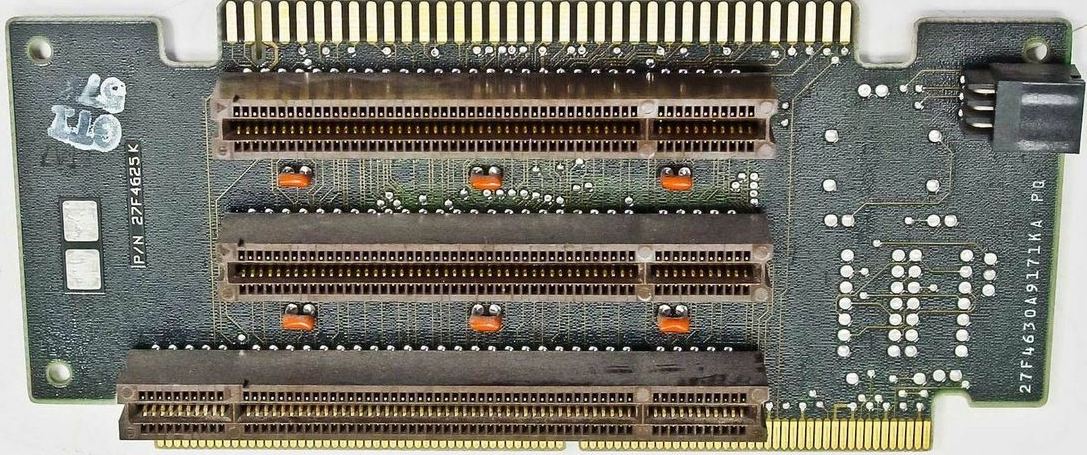
Newer
Riser P/N 27F4625 / 64F0774 This riser has an addition of a resistor, a 74F08N, and
a bit of wiring on the back. Late
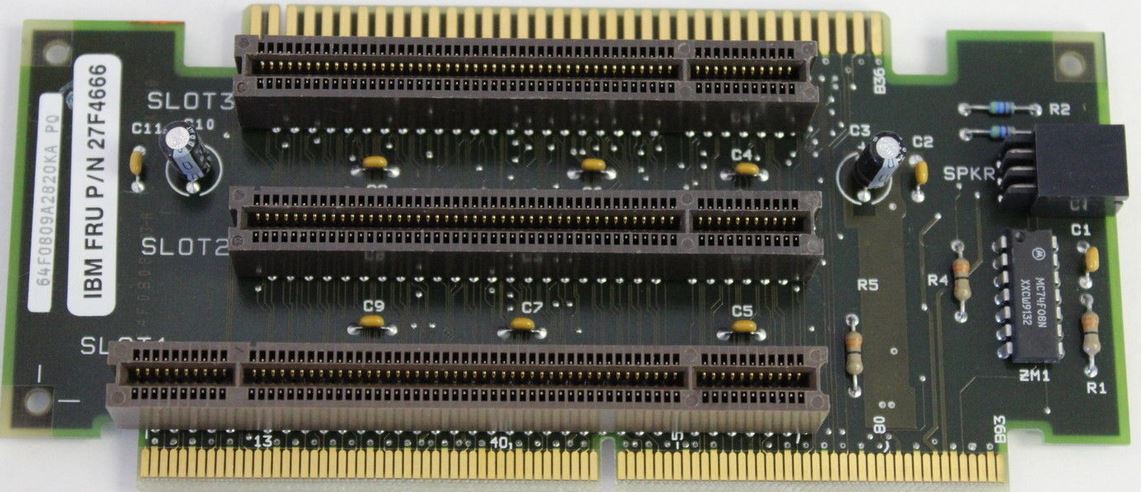
Riser P/N 27F4666 / 64F0809
ZM1 MC74F08N 64F0809 takes care of hangs with the 8514/A card. Supports 1MB and 2MB 100nS and 85nS SIMMs. Model 55 Tech Ref, 2d Ed, claims 4MB/80nS support. [55SX -041 / -081, 55LS -LE0 / -LT0] The PS/2 Models 55 SX and LS are compatible with: FEATURE PART DESCRIPTION NUMBER NUMBER SYSTEM BOARD MEMORY PS/2 1MB Memory Module Kit-85ns 5212 6450603 PS/2 2MB Memory Module Kit-85ns 5213 6450604 PS/2 4MB Memory Module Kit-80ns 3933 87F9977 8555 -031 / -061 o 1Mb Memory Module Kit (85ns) (#5212) (6450603) o 2Mb Memory Module Kit (85ns) (#5213) (6450604) 8555 Diskette Drive Connector Not the same as in the HITR. Figure 3-5, page 3-8 of the Model 55 Tech Reference.
Type 2 Serial Port Controller Some Type 2 serial controllers used on the Model 55 system board do not respond as described in the Hardware Interface Technical Reference. After the FIFO mode is enabled, bit 6 of the Interrupt Identification register is erroneously set to 0, indicating a Type 1 serial controller is installed. Any application program or operating system that uses bit 6 of the Interrupt Identification register as an indicator to determine FIFO support will default to the character mode. This indicator is ignored by the Model 55 ABIOS. Therefore, programs that operate through ABIOS can use the FIFO mode. The ABIOS routines also clear any error indications remaining after a mode change. Some application programs reset the received-data-ready indication by writing bit 0 of the Line Status register as a O. This method can cause compatibility problems and is not supported by Type 1 or Type 2 serial controllers. To avoid compatibility problems, bit 0 of the Line Status register can be reset to 0 by reading the data and discarding the data if it is not used. • The Model 55 supports FIFO through ABIOS calls only. Type 1 Parallel Port Controller (?) Bi-Directional, no DMA. > No, it doesn't get to the menu. It just says that the battery is dead then starts the Automatic Configuration (or, at least, attempts to). I tried unplugging everything and the plugging them one by one, but without any luck. It does the same thing every time... Peter says: After a power cycle and reboot from the reference
diskette the silly game repeats. CMOS Clear Method Aron Eisenpress comes up with: "I have exactly the same problem with a 55SX.
Only in my case I was trying to install OS/2 on
it. The install progressed to the first reboot and
then couldn't boot off the drive. What's weird is
that it manages to copy all the files to the drive
during the installation, so it does see the drive, it
just won't boot from it. Aron suggested the following, but I haven't had a
chance to try it yet. I have to look for a DOS
floppy to boot from. If you try this and it works
please post it here. "I did some searching on the 55sx problem after
replacing the Dallas RTC chip, and found one suggestion
that says you need to clear the CMOS before the
configuration will take. The method is to boot from a floppy, run DEBUG, and
type o 70 13 Color Changes After Memory Upgrade I keep losing half my color settings in Windows whenever I increase the ram chips from 2 meg to four meg. Does anyone know what settings are being changed (INI files, resolution)? Any tips welcomed. Peter replies: I would suggest to try out a "bread board" installation. Remove the board from the chassis, remove the power-supply also and place it on a non-conductive surface (Warning: underside pins may scratch furniture). Install the memory modules, the riser board and lay HD and FDD in a place where it can be connected but do not touch board or power-supply. When the system runs fine without the chassis inspect the underside of the planar if there are cracks or too long component pins, especially on the riser-card connector and around all places, where the board fixing screws go. And: there are some combinations of planars / riser-cards known as non working. If the planar FRU is 27F4667 the appropriate riser-card must be 27F4666 (P/N 64F0809 on a white sticker, contains a 74F08-chip and some condensors / resistors. The almost totally empty riser-card (P/N 274630 on white sticker / 6 condensors between slots / 2 larger tinned areas at the rear) belongs to an early down-level 55SX-planar and is known to cause problems. The 2nd series risercard . Peter wrote: It is pretty hard to tell which boards are affected. I found out during testings, that mainly those old boards tend to fail that have the "dead cockroach" chip at the mid/front. It is sitting between the two bigger square chips and is accompanied by a silver capped chip glued to the board. Both are wired to the system with patch-wires. These machines have the old Level-1 riser card 27F4630 (printed on a decal), which is almost bare apart from six small condensors between the MCA connectors. The Level-1 riser board has no chips and no "component printing" in white. The board P/N is 33F5064 (sticker over 33F5060 P/N - which was the buggy, unfixed original board P/N). There was a revised systemboard without
the patch-on chip, which came with the Level-2 riser
(several resistors, some el-co's and the small
condensors - came with an ECA from IBM due to problems
running 8514/A style cards), which has been replaced by
the Level-3 riser 64F0809 with a 74F08 chip (ZM1). The
early 55SX planar cannot be used with the Level-3 risers
... the later systemboard should not be used with the
bare Level-1 riser. The later sysboard is FRU P/N 27F4667, P/N 85F0419 (55SX) or 57F3003 (55LS / LEO/LTO - which have the additional 2K CMOS NV-RAM), the riser is FRU P/N 27F4666, P/N 64F0809 (55SX) or 64F3732 (55LS). Sadly the FRU alone does not tell, which P/N is behind ... IBM always delivered the latest P/N at a FRU request. I installed about 350 - 400 Mod. 55SX in the early '90s for the german Automobile Club ..... so I guess I knew them quite well ... :-) The harddisk is in fact a camouflaged MCA-adapter with
a harddisk mechanism atop. The maximum system board memory capacity is 8MB (4MB
memory module kits installed in memory-module connector
1 and 2). A memory-module kit must be installed in
memory My experience is that the 55sx is fine with one SIMM,
but it must go in the slot closer to the power supply.
The 55sx takes PS/2 SIMMs, 1mb, 2mb, or 4mb, either 85ns
or 100ns. I'm pretty sure it can also take 80ns
SIMMs (definitely can in the 4mb size), but I'm not
certain. 486 CPU Upgrade: IBM PS/2
Model 56, 57 Older 55SX had a slightly buggy mainboard / CPU where the "CPU disable" pin did not work as supposed. You could use "clip-over" upgrades only on the 55SX anyway since it has no "upgrade" socket of any sort (the 387SX socket does not feed all required lines through ...). If your 55SX planar has the "dead cockroach" fix (silver capped chip with patchwires around) suspect it as one of the earlier ones that might or might not work. The early models with the "bare" riser card without any TTL-logic chip and without lots of capacitors had multiple troubles - not only with the CPU. >But could you ground out a pin directly on the cpu? Ahem ... as far as I recall IBM reported having got a quantity of 386SX where the disable pin does not work *at all* - and therefore any clip-over upgrades won't work. The "dealer confidential" paper I have in mind mentioned the 55SX / 65SX only - none of the other SX-machines (like L40, N33 etc.) where the case forbids to use any updates anyways. The L40 however had been on the "CPU upgradeable" list at Hantz & Partner (www.upgrade.de) years ago, which was a "send-in upgrade" with soldering on board level. So it seems as if only very early 16MHz 386SX were affected by this general fault. The corresponding pin is -FLOAT ("FLT#", active low - pin 28), which "floats all Intel 386SX bidirectional and output signals, including HDLA. Asserting FLD# isolates the Intel 386SX from the surrounding circuitry." (Intel Datasheet 24018708.PDF, Page 60) Originally this pin was added to allow in-circuit emulation without the need to unsolder / remove the chip from the board. Simple test: ground pin 28 and the system may not POST. If it does the chip is one of those faulty few. 386SX/16 CPUs in general do not have a (working) disable pin, except they bear a 'C STEP' writing (most of the ones I've seen don't...). All 386SX CPUs with 20 MHz or more use at least the C stepping mask, so that's not a issue for them... Best regards, Alfred Remove Password Password is gone. ADF Sections for @DF9Fh "Integrated Fixed Disk and Controller" DMA Arbitration Level DMA channel adapter uses to transfer data < "Level 5">, 6, 7, 0, 1, 3, 4 DMA Burst Pacing Interval Time interval between DMA transfer bursts during which the Micro Channel is released by the fixed disk controller for use by the CPU. Under normal circumstances, select <24 Microseconds> <"24 Microseconds">, 31, 16, Burst Disabled DMA Pacing Control Enables or disables the 'DMA Burst Pacing Interval.' If set to <Burst Disabled>, the DMA Pacing Control will be disabled. Under normal circumstances, select <Disabled>. <"Disabled>, Enabled Time to Release The amount of time that the fixed disk controller will keep the Micro Channel after being preempted. If the 'DMA Pacing Control' is set to <Enabled>, the Time to Release will default to immediate. Under normal circumstances, select <6 Microseconds>. <"6 Microseconds">, 3, Immediate Fairness On/Off Whether the adapter will release control of the bus when it has been using it exclusively. Under normal circumstances, select <On>. <"On">, Off Primary/Alternate Port Addresses Port addresses used by the adapter. Either <Primary> or <Alternate> will work equally well. If there are two integrated fixed disks, then select <Primary> for one and <Alternate> for the other. <"Primary"> (3510h-3517h), Alternate (3518h-351fh) |