|
rf70486a.exe PS/2 8570 486 ref disk v1.06 For IBM planars, NOT Reply planars. Xgaopt.exe Installs updated ('92) SC.EXE, XGA/2, SCSI, SCSI w/cache ADFs, plus updated *.dgs. For 5565, 5657, 70486, 7080, 7677, 90, 95, P70, P75. 191-079 PS/2 MODEL 70 386 (081, 161, A81 AND A16) 189-144 New Models of IBM PS/2 Model 70 386 (8570-061 and 8570-A61) 188-079 PS/2 MODEL 70 386 (8570 E61/121) 188-078 PS/2 MODEL 70 386 (8570-A21) SHS64F3993 IBM PS/2 Model 70 HMR SHS15F2197 IBM PS/2 Model 70 HMS Type 1 Planar (full size, 16 and 20 MHz) Type 2 planar (short size, 16 and 20 MHz) 25MHz planar (-Axx 386DX-25, -Bxx 486DX-25, same planar) Reply Upgrade Planar only! [486DX and BL2-66 use same system board!] 70_FLASH.EXE 8570 planar upgrade flash BIOS v1.18.02 rf70plan.exe 8570 planar upgrade reference diskette Reply 8570 OEM Planar 486DLC2 System Board Upgrade PN 71G2610 FRU 13H6701 "Blue Lightning" IBM PS/2 486DX33 Processor Upgrade [8570 92F0436, 8580 92F0437] 8570 PSU (similar to 8550, 7561) Tim's IBM
8570 web pages (Mostly salvaged) Mouse
Locking Up 8570 During Boot Memory Min/Max on system board: 1/6MB (Exx,1xx), 2/8MB (Axx/Bxx) (expandable to 16MB) 85ns SIMMs on 16MHz and 20MHz planars, 80nS SIMMs on 25MHz planars ROM: 128kb Cache: 0kb (Exx), 0kb (1xx), 64kb SRAM L2 cache (386 25MHz planar only) 8570 Models ** These models can
be upgraded with the 486DX-25
"Power Platform" and BIOS upgrade chips, making
them a true 8570-486. The planar is shown on the 8570-486 page Mouse Locking Up 8570 During Boot Konradin Stenner wrote: During boot happens nothing when the mouse, no matter which one I use, is connected. The monitor does not go from standby to operate mode, there is no harddisk or disk access to see. When the mouse is disconnected system does boot. When I connect the mouse during the boot, it works fine. Dr. Jim Shorney [Computer Repairman to the Stars] Clean the system board and power supply with compressed air. An excessive buildup of dust can cause strange problems. Also, this may sound totally off-the-wall, but try a different keyboard. The KB and mouse use the same controller. Or, the mouse port connector could be worn out or damaged, have broken solder connections, etc., which could be causing a latchup of the data lines when a mouse is plugged in. Konradin reports success Thanks all, and special thanks to Jim, who had the right idea! The DEC keyboard was changed to a Dell keyboard and now the machine does boot. Opening a Locked 8570 Case (w/o a key!) From Peter Unscrew the two rear thumbscrews, push the upper case forward as far as possible .... then use a large flat blade screwdriver between upper case and rear wall and lift up the case for about 4 - 5 mm and push it over the lock .... Once having it open you can pull out the lock fixing bracket and remove the cover lock from the rear wall. You see: a potential intruder might only try hard enough to get in ... *thieves* steal the entire machine and break it open at home :-) Loosen cover screws. They are captive, so when they
turn free, they are done.
Slide the case forward about two inches then lift up. 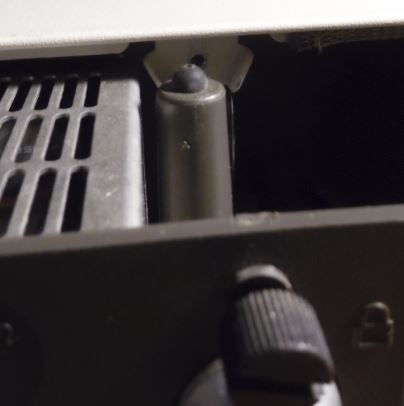 This is a closeup on a weight transfer point. Notice the little rubber bumper on top? The four towers on the drive shelf transfer the weight of any monitor directly to the base. No flexing of the planar. Thing of the issues that the 55SX had with monitors on top of the case, pressing down on the drive riser and flexing the planar. Closing 8570 Case - Rear Case Guide 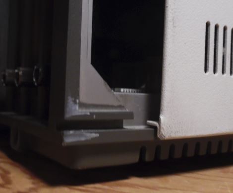 Place cover on base with about 1" between the rear of the case and the rear of the top cover. The top cover should now slide easily into the case guide at the bottom rear of the case. If your cover is not mating, check this fit. The floppy _may_ be a bit misaligned, preventing it from easily fitting into the front bezels. This is uncommon, check on whether the floppy is fully seated on the drive shelf.
Remove/Install the Planar Pull the floppy, hard drive, and drive riser. Pull the PSU. (not in any particular order). Pull up on all of the white plastic snaps (get the one under the battery, too!). Pull the drive structure straight up. If it doesn't come up, check the white snaps again plus the slotward case screw. Slotward Case Screw Too Far Forward 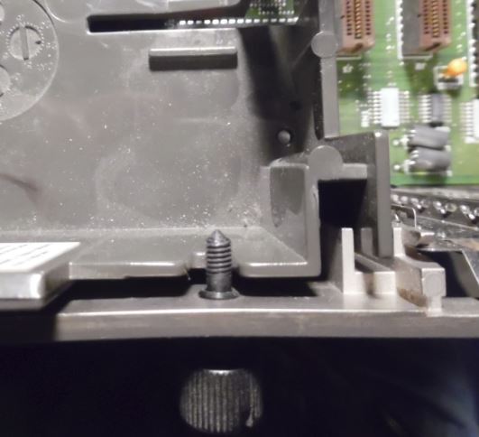 Remove the screws holding the planar down (only three!). One in the front of the 16 bit video slot, one to the front left of the video port, and one cunningly hid under the PSU fan... Bet that is a 8550 mounting point and IBM just left it alone. 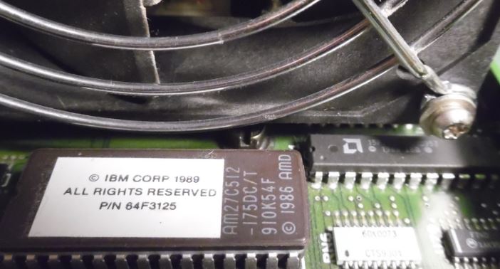 Remove the three screws at the back of the system (right above the ports). 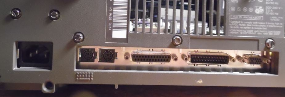 There are three screws holding the planar EMC bezel to the rear of the case. To show the thoroughness of the design, there is a small 1/8 inch pin coming up from the base. It precisely mates with a small hole by the big inductor LN2. This small pin positions the planar left to right exactly, as well as front to rear. The planar MUST be lowered straight down onto the base. Positioning Pin 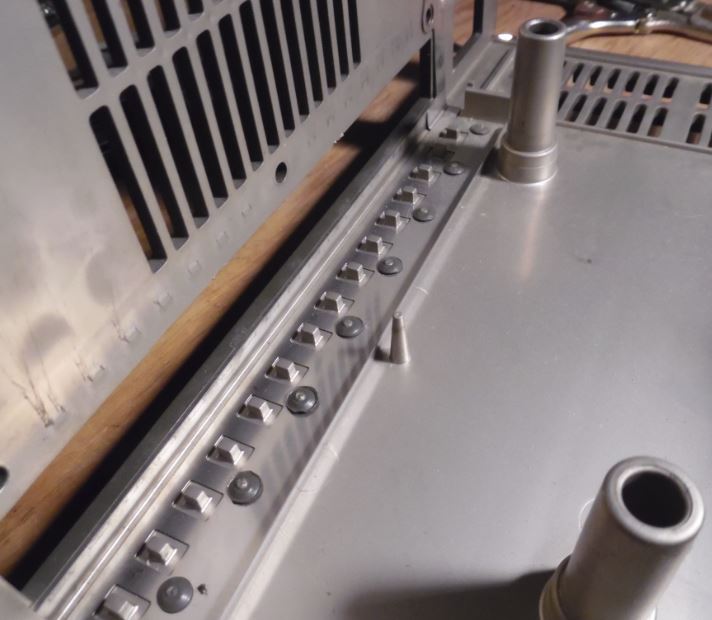 Location of Planar Positioning Pin 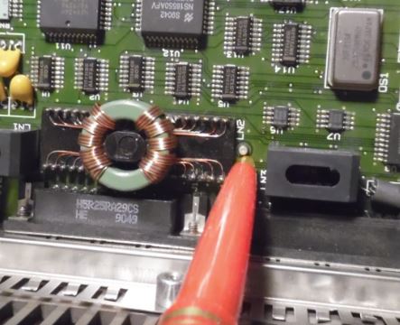 Now for all you 95 veterans, read carefully! Lift the planar straight up! The planar is positioned exactly with a pin at the rear of the case. You may need to put your fingers in the port opening in back and pull up- the EMC bezel exerts force on the positioning pin. When reinstalling a planar, you will know when it isn't fully seated- the screws from the back will be too low to thread into the mounting points. Think of the engineering. Everything is positioned in relation to the rear of the case (planar and PSU). The planar is positioned pretty close, once down on that pin, the holes through the planar are darned close to dead on aligned with the threaded inserts in the base. The PSU slides in from one direction, and when it seats on the planar edge connector, it is aligned with the two holes in the back of the case. There is a little wiggle room, but the PSU more or less drops right in. Love it. Precision where it matters
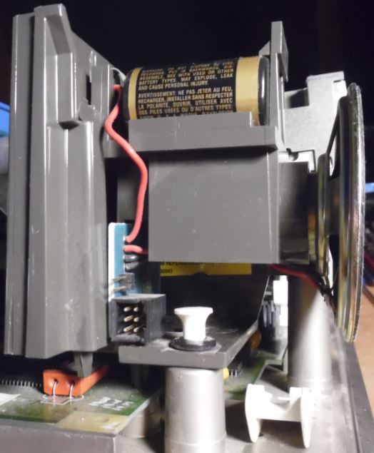
Pinout for Battery/Speaker connector
Clear a Power-On Password 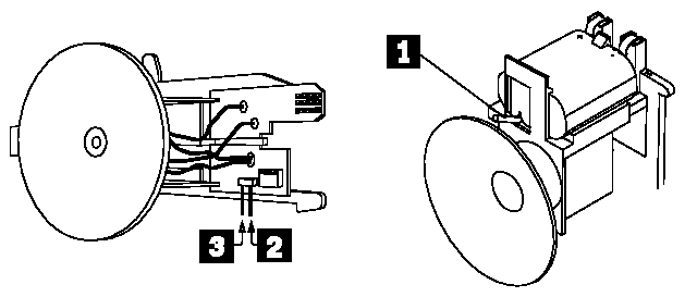 Model 50, 60, 70, 80 Override Jumper 1.Power-off the computer and unplug the power cord. 2.Remove the system-unit cover. 3.If the speaker assembly has pins, short pins 2 and 3 together. 4.If the speaker assembly does not have pins, insert a meter lead into connector 1 and short the other end of the lead to frame ground. With the assembly shorted, power-on the computer. This
erases the power-on password. Remove the short after
POST is finished. Speaker Assembly with Pins Note the six pin header? I have seen headers with a
short cable that plugs into the matching six pin header
on short 8570 boards and 8580 as well (IIRC). IIRC, the
wires are red and black. To remove the battery assembly, push inward on the
catch at the bottom. In this picture, you can see the
end of the catch right over the orange XTAL holder.
While pressing in, push or pull the assembly UP. It is
not loose, because it has to be snug enough to inset the
edgecard into J19. Remember, IBM automated assembly, so
things could not flop around... Overclocking to 33MHz Alban Kellerbauer wrote: ========== Some of you may remember that I repeatedly inquired about other people's experiences with overclocking PS/1 and PS/2 machines, where by overclocking I mean replacing the clock oscillator with a faster one. Since nobody seems to have done this before, I had no choice but to try it myself. I have a model 8570-061 that came with a 386DX-20 running, obviously, at 20 MHz (clock oscillator at 40 MHz). I de-soldered the oscillator and inserted a full-size oscillator socket (there are solder holes for either a half-size or a full-size oscillator). The socket permitted me to try different oscillators without soldering and de-soldering more than once. I found the socket in the Digi-Key catalog (part number A462-ND). I then replaced the CPU with a 386DX-33 and inserted first a 66 MHz oscillator (Digi-Key part number CTX137-ND), which didn't work, and then a 50 MHz oscillator (part number CTX121-ND), which worked. Just in case that wouldn't work either, I had also bought a 40 MHz oscillator (part number CTX120-ND), because the de-soldered oscillator's legs are not long enough to firmly sit in the socket. I had the 8570 running DOS and Windows 3.0 running for several hours without any problems. AdapterID DF9F Integrated Fixed Disk and Controller DMA Arbitration Level
DMA Burst Pacing
Interval DMA Pacing Control
Time to Release Fairness On/Off Primary/Alternate Port
Addresses |
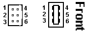 6 pin
Header
Edgecard Socket
6 pin
Header
Edgecard Socket