EMC - Embedded Modular Computer
EXM - EXpansion Module
Inserting an EPC into an EXM Carrier
NOTE: Make sure that power to your system is off. The EPC-23 is not designed to be inserted or removed from a live system.
NOTICE: Use of any of the files or information on this page is AT YOUR OWN RISK. If you want a guarantee on this stuff, seek out any repair / service company that supports EXM / EPC devices.
If you have any files or experience with these devices, you can reach me HERE
EPC-2x Type Index
Type 1 - EPC-21 / -22 Based on 386SL
Type 2 - EPC-23 Based on 486SL
Type 3 - EPC-24 / -25 / -26 Based on 486 Enhanced (3.3v SIMM)
Type 4 - EPC-26A / -27 Based on 486 Enhanced, Pico Power chipset (3.3v SIMM)
EPC "Types"
I know Radisys never grouped their EPC-2x into "Types", akin to IBM's processor complexes. But if you look at the Radisys documentation, the -21/-22 share the same archive, the -23 is alone, the -24/-26 share the same archive, and the -26A/-27 share the same archive.
EPC-5/-7/-8 vs EPC-2x
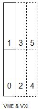
| VME / VXI
Carrier |
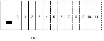
EMC Chassis |
 |
 |
VME / VXI system EPCs already have a system board as part of their chassis. They CANNOT accept an EPC-2x module and function. The EXM bus does not support ISA busmasters. VME / VXI can host many of the EXM modules. Check the EXM module's documentation.
EMC based systems accept any EXM size format EPC-2x CPU module. The EXM bus does not support ISA busmasters.
NOTE: If you want to impress me, get a EXM-12 Prototype module and make a busmastering support circuit.
The Mysterious EPC-25
There is a gap in the EPC numbering convention, -25. It may be the way it is, but I have read ONE press release that said
i486 options for embedded control HERE
This article was posted on 06/01/1994
Board comes with three 486 options for embedded control: 25-MHz 486SX, 33-MHz
486DX, and 50-MHz 486DX2; all come with up to 16 MBs of RAM, 128 KB of
battery-backed SRAM, and 2 MB of flash memory; a serial port and a keyboard
port are included along with a PC-compatible BIOS; available now.
EPC-24/25/26
From $785
RadiSys Corp.
Beaverton, OR
Steve Verleye 503-646-1800
Radisys ECP Processor Module Ports (EXM Format)
WARNING: Some EPC modules are incompatible with other modules or carriers. Please read the documentation from Radisys. Do NOT assume the EPC format module is compatible in your application!
No BIOS flash images to be found for any EPC-2x
EPC-2x CPU Module Ports
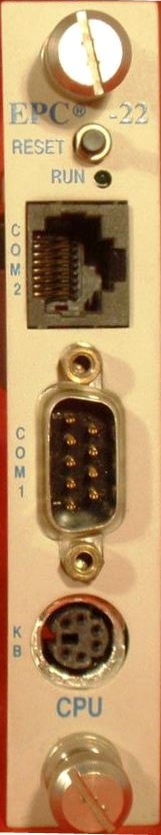 |
Although this is an EPC-22, all
EPC-2x CPU modules have the same ports. RESET - causes EPC to perform hardware reset. The system will run POST and reboot the operating system RUN - LED lit during memory access. It comes on at power-up and stays lit while system is running. It normally flickers during power-up. If CPU halts (or hangs) , the LED will go out. COM2 - RJ45 COM1 - DB-9 DTE serial port KB - 6-pin DIN AT only? Does not accept PS/2 keyboards? Battery - Panasonic BR2330 or Rayovac BR2335 |
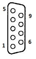
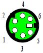
COM1 Serial Port (DB-9)
|
|
Pin |
Signal |
Pin |
Signal |
|
|
1 |
DCD |
6 |
DSR |
|
2 |
RxD |
7 |
RTS |
|
|
3 |
TxD |
8 |
CTS |
|
|
4 |
DTR |
9 |
Ring
indicator |
|
|
5 |
Ground |
|
|
COM2 Serial Port (RJ45)
|
|
RJ45 |
Signal |
DB25 |
|
|
1 |
Shield |
1 |
|
2 |
CTS |
4 |
|
|
3 |
TxD |
3 |
|
|
4 |
DTR |
8 |
|
|
5 |
RxD |
2 |
|
|
6 |
DCD |
20 |
|
|
7 |
Ground |
7 |
|
|
8 |
RTS |
5 |
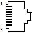
Oh, ho... So there was an RJ45 to DB-25 cable. RJ45 to DB-9 should be possible.
EPC-2x Keyboard Port
|
|
Pin |
Signal |
Pin |
Signal |
|
|
1 |
Data |
4 |
+5V |
|
2 |
not used |
5 |
Clock |
|
|
3 |
Ground |
6 |
not
used |
NOTE: Though this is a mini-DIN 6 pin socket, it might not support PS/2 keyboards.
So why the fuss over AT keyboard? Just to ensure any old Radisys keyboards can be used with an AT to PS/2 adapter?
Battery - Panasonic BR2330 or Rayovac BR2335. All CMOS values will be lost when you pull the battery.
Substituting a CR2032
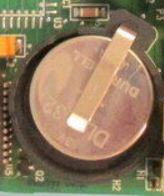
Well. A 2032 coin cell will work, it is only 20mm in diameter. The two listed batteries are 30mm and 35mm in height.
Floppy Types Supported
The EPC-2x support 360K, 720K, 1.2 MB, 1.44MB, and 2.88 MB. BUT... If you look at the EMC-FDM, it appears to have a max 500Kbit/s transfer rate, which suggests to me that it tops out at 1.44MB floppies.
So if you want 2.88MB floppy support, you might have to choose an EXM module with an external floppy header.
Configuring an EXM Module
My guess is Radisys could not emulate IBM's autoconfiguration, due to patents. The EXM bus has a signal, EXMID, that sure resembles POSID. But for reasons known only to God, you have to manually calculate and populate three hexadecimal byte-pairs, ID, OB1, OB2.
Finding ID, OB1 and OB2 Values
Look in the Radisys documentation, usually Chapter 2.
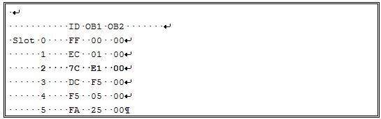
Example: Configure EMC-FDM (COM, LPT, Floppy)
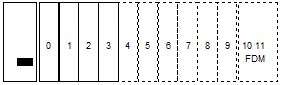
The EMC-FDM occupies the two open slots on the far right of the chassis.
Bits to Hexadecimal
You will notice that the OBx documentation lists bit values of 1 or 0, and there are 8 digits (bits). Again, look at the Radisys documentation for that module, and specifically in Chapter 2. Take your time, because the tech writing is indifferent...
The leftmost bit (bit 7) is the highest value (Most Significant Bit). Bits 7-4 are the hexadecimal left byte, bits 3-0 are the hexadecimal right byte.
I use the format of 0 0 0 0 - 0 0 0 0 because it is easier to distinguish the bits for the left Hexadecimal byte from the bits for the right Hexadecimal byte.
Decimal - Binary - Hexadecimal Chart
|
DEC |
BIN |
HEX |
|
0 |
0000 |
0 |
|
1 |
0001 |
1 |
|
2 |
0010 |
2 |
|
3 |
0011 |
3 |
|
4 |
0100 |
4 |
|
5 |
0101 |
5 |
|
6 |
0110 |
6 |
|
7 |
0111 |
7 |
|
8 |
1000 |
8 |
|
9 |
1001 |
9 |
|
10 |
1010 |
A |
|
11 |
1011 |
B |
|
12 |
1100 |
C |
|
13 |
1101 |
D |
|
14 |
1110 |
E |
|
15 |
1111 |
F |
NOTE: Yes, there are sixteen Hexadecimal values (0-F), remember that 0 (zero) is one of them. So Hexadecimal goes up to 15 Decimal.
Award EXM Setup (EPC -21/22/23)
Phoenix EXM Setup (EPC -24/25/26/26A/27)
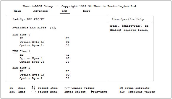
ID Byte is a hard-wired ID value. The EMC-FDM should be set to 7C
OB1/OB2 are two bytes of option information [Option Byte or OB].
NOTE: slots without EXM module have ID of FF and OB1/OB2 of 00 00.
Calculate OB1 and OB2
OB1 Bytes
|
(bit 7) |
(bit 6) |
(bit 5) |
(bit 4, 3) |
(bits 2,1) |
(bit 0) |
|
Parallel Port I/O Enable |
Parallel Port Enable |
Printer Port Select |
COM Port Interrupt |
COM Port Base Address |
Card Enable |
|
1=Enable output 0=Enable input |
1=Enable 0=Disable |
1=378, IRQ7 0=278, IRQ5 |
00=Disabled 01=IRQ3 10=IRQ4 11=IRQ9(2) |
00=Disabled 01=2F8h 10=3E8h 11=2E8h |
1=Enable card 0=Disable card, IRQs |
Disable
LPT and COM, but enable card (floppy
support)
0 0 0 0 - 0 0 0 1
binary, becomes 0 1 in
Hex.
Enable LPT for printing
[output], disable COM, enable card.
1 1 1 0 - 0 0 0 1
binary, becomes E 1 in
Hex.
NOTE: Remember the
EPC has >TWO< COM ports, so you'd better be
cautious
on enabling the EMC-FDM's COM port.
NOTE: In general, attaching a mouse to a serial port only works on COM1 or COM2.
OB2 Bytes
|
(Bits
7-2) |
(bit
1) |
(bit
0) |
|
Masked |
Reserved |
Floppy
drive enable |
|
1 1 1
1 1 1 |
1=
default |
1
= Enable floppy drive, DRQ and IRQ 0
= Disable floppy drive |
Simple, bits 7-2 are masked to 1, bit 1 is reserved, and bit 0 enables the floppy drive.
Enable Floppy Drive
1 1 1 1 - 1 1 1 1 binary, becomes F F in Hex.
NOTE: This is OB2, not ID. An OBx value of FF does NOT mean empty.