Radisys Embedded
Personal Computer (EPC)
EMC - Embedded Modular Computer
EPC - Embedded Personal Computer
EXM - EXpansion Module
Some manuals date from 1992 (maybe 1990 on a few). So... they might be a bit outdated for modules made in the mid 1990s. Also, the version of Word used for the early manuals is Word 2.0, which is right out if you are using Word 2003. It requires adding a registry value to allow Word to open the old file....
EXM is a mix between ISA and VME. Thankfully, most modules act as ISA cards to any operating system. So you could probably install using common drivers and it should work. Most EXM do not have specific drivers, but there are a few based on old chips dating back to 1989 or so, and they may lack support from more modern operating systems.
NOTICE: I have NO personal experience with any Radisys EXM related system or components. All these files were retrieved via Internet Archive and were re-named to a shorter format. To me, there can only be one period in a file name, or you may get odd problems with web pages...
Use of any of the files or information on this page is AT YOUR OWN RISK. If you want a guarantee on this stuff, seek out any repair / service company that supports EXM / EPC devices.
If you have any files or experience with these devices, you can reach me HERE
Radisys EXM Modules
WARNING: Some EXM modules are incompatible with other modules or carriers. Please read the documentation from Radisys. Do NOT assume the EXM format module is compatible in your application!
These modules have utilities that can be used with the EPC-26A/27 Flash/SRAM.
EXM-2 Flash Disk (Flash)
EXM-2 Manuals 2_v104
EXM-2A Solid State Disk Module (Flash and SRAM)
EXM-2A Manuals 2A_v100
Radisys ECP Processor Modules (EXM Format)
WARNING: Some EPC modules are incompatible with other modules or carriers. Please read the documentation from Radisys. Do NOT assume the EPC format module is compatible in your application!
No BIOS flash images to be found for any EPC-2x
EPC-2x CPU Module Ports
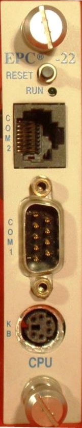 |
Although this is an EPC-22, all
EPC-2x CPU modules have the same ports. RESET - causes EPC to perform hardware reset. The system will run POST and reboot the operating system RUN - LED lit during memory access. It comes on at power-up and stays lit while system is running. It normally flickers during power-up. If CPU halts (or hangs) , the LED will go out. COM2 - RJ45 COM1 - DB-9 DTE serial port KB - 6-pin DIN AT only? Does not accept PS/2 keyboards? Battery - Panasonic BR2330 or Rayovac BR2335 |
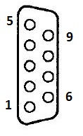
COM1 Serial Port (DB-9)
|
Pin |
Signal |
Pin |
Signal |
|
1 |
DCD |
6 |
DSR |
|
2 |
RxD |
7 |
RTS |
|
3 |
TxD |
8 |
CTS |
|
4 |
DTR |
9 |
Ring
indicator |
|
5 |
Ground |
|
|
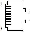
COM2 Serial Port (RJ45)
|
RJ45 |
Signal |
DB25 |
|
1 |
Shield |
1 |
|
2 |
CTS |
4 |
|
3 |
TxD |
3 |
|
4 |
DTR |
8 |
|
5 |
RxD |
2 |
|
6 |
DCD |
20 |
|
7 |
Ground |
7 |
|
8 |
RTS |
5 |
Oh, ho... So there was an RJ45 to DB-25 cable. RJ45 to DB-9 should be possible.
EPC-2x Keyboard Port
|
Pin |
Signal |
Pin |
Signal |
|
|
1 |
Data |
4 |
+5V |
|
|
2 |
not used |
5 |
Clock |
|
|
3 |
Ground |
6 |
not
used |
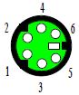
NOTE: Though this is a mini-DIN 6 pin socket, it might not support PS/2 keyboards.
So why the fuss over AT keyboard? Just to ensure any old Radisys keyboards can be used with an AT to PS/2 adapter?
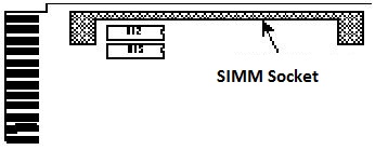
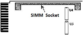
Folks, I am confused, there are no pictures of EPCs with the SIMM removed, and that obscures the components below.
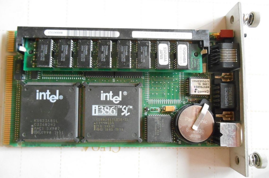
Intel386 SL Microprocessor SuperSet
KU82360SL Complete ISA Peripheral Subsystem Advance Information
KU80386SL 386SL CPU DataBook Jul92
64KB Cache
The two ICs under the center of the SIMM are the 64KB cache, CY7C195-25VC
CY7C195-25VC 64K x 4 Static RAM datasheet
N8242 (?)
N8242 (?) Universal Peripheral Interface 8-Bit Slave Microcontroller
Not sure, bet this is mask programmed with my kinda luck... AWARD BIOS for EPC, but the N8242 says "Phoenix". So which keyboard does it support?
Battery - Panasonic BR2330 or Rayovac BR2335. All CMOS values will be lost when you pull the battery.
Base Memory 1MB or 4MB
1 MB of base memory uses 2 4Mbit chips (two 256K by 18-bit banks). There are 42 pads per chip but the chips are 40-pin. Therefore the rear-most pads are not used.
4 MB of base memory uses 2 16Mbit chips (two 1MB x 18-bit banks). All pads are used for this memory configuration.
EPC-21 CPU (16 MHz Intel 386 SL)
Supposedly, the 16MHz version lacks the 64KB cache and no 387SX. Does this mean the -22 has two variants, or did Radisys use 25MHz rated CPU and only clock it at 16MHz? SIMMs cover the components, so I'm not sure...
EPC-21 Manuals
EPC-22 CPU (25 MHz Intel 386 SL / 387)
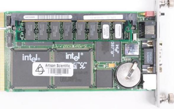
4MB EPC, all solder pads are used for the Base Memory. The 64KB cache is dead-center under the SIMM, and the 387SX is on the right.
EPC-22 Base Memory
EPC-22 Manuals
EPC-23 CPU (25 MHz Intel 486 SL)
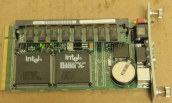
Notice that there are solder pads for Base Memory.
EPC-23 Base Memory
The EPC-23 has a base memory of 0 MBs or 4 MB. The 4 MB base memory is soldered on.
80nS FPM SIMM, single-sided or thin double-sided (uses TSOP packaged DRAMs)
EPC-23 with 0MB Base Memory, 4MB or 8MB SIMM, max 8MB.
EPC-23 with 4MB Base Memory, 4MB or 8MB SIMM, max 12MB.
EPC-23 Manuals
The EPC-24/26 are all derived from a single design. Based on the Intel486 Enhanced chip set, all front panel accessible ports have filter networks for reduced EMI and increased ESD protection
EPC-24/26 may come with 128 KB of SRAM and 2 MB of flash memory. The EPC-24/26 does NOT have a Base Memory option.
72-pin 3.3V SIMM, 4/8/16 MB, 80nS FPM SIMM, single-sided or double-sided
H3 Jumper? Flash write enable?
EPC-24 CPU (25 MHz 486 SX Enhanced, 3.3v SIMM!)
EPC-24 Manuals
EPC-26 CPU (50 MHz 486 DX2 Enhanced, 3.3v SIMM!)
EPC-26 Manuals
Sequoia-1 PT86C768A2 Pico Power System Logic
PT86C718 Pico Power IDE Interface, Peripheral Controller, Interrupt Multiplexer
EPC-26A CPU (50 MHz 486 DX2 Enhanced, 3.3v SIMMs, "Redwood" PicoPower)
EPC-26A Manuals
EPC-27 CPU (100 MHz 486 DX4 Enhanced, 3.3v SIMMs, "Redwood" PicoPower)
EPC-27 Manuals
EPC-26A/27 Jumpers
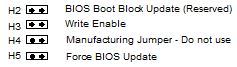
H2 Reserved for future use.
H3 Use to enable writing to flash
H4 Do not use
H5 Forces a hosted re-flash of the BIOS. Must jumper H3 also.
Optional Flash/SRAM Memory
The EPC-26A/27 can have 128 KB of SRAM and 2 or 4 MB of flash installed on it. The EPC Flash/SRAM is compatible with the EXM-2A architecture and it appears to software as though there was an integrated EXM-2A in the system.
NOTE: Software cannot distinguish EPC Flash/SRAM from a separate EXM-2A card using the same configuration. A system cannot enable both the optional Flash/SRAM and an EXM-2A expansion module at the same time.
Note that the XFORMAT program used to format flash memory is also distributed with the EXM-2 and EXM-2A expansion modules. Any references to the EXM-2 and/or EXM-2A are intended to denote your flash memory.
Refer to the XFORMAT Software User’s Manual for more information about formatting SRAM and flash memory.
FLASH and SRAM
Formatting the FLASH memory and creating a bootable drive will take over as the C:, this prevents any DE drive from working. Look in the EXM-2A files for XFORMAT and SRAMDISK.
XFORMAT.EXE Flash formatting program
SRAMDISK.SYS SRAM device driver
BB5.00 Boot block files for DOS 5.0
BB6.00 Boot block files for DOS 6.0, 6.1, & 6.2
Booting From Flash Memory Conflicts with IDE Drive
If you plan to boot from a non-IDE device, such as the resident Flash memory, set the master drive as None and use the BIOS extension. You cannot boot from Flash and still have an IDE drive; the IDE drive must be drive C: if it is to be used. Flash BIOS extensions are enabled and configured in the Advanced Menu.
To use an EXM-HD or EXM-MX series mass storage unit, you must configure a master adapter;
Floppy Types Supported
360K, 720K, 1.2 MB, 1.44MB, and 2.88 MB. BUT... If you look at the EMC-FDM, it appears to have a max 500Kbit/s transfer rate, which suggests to me that it tops out at 1.44MB floppies.