|
A long time coming, but worth it. Operator Panel
(another page) Mounting
Hardware
Open Case 1. Remove front bezel:  a. Unlock bezel. (what key?) a. Unlock bezel. (what key?) b. Grasp bezel at bottom and firmly pull it out from server. c. Remove top corners of bezel from server. NOTE: Do NOT twist bezel to one side!. The pivot points WILL snap if you apply too much crosswise force. 2. Remove Access Cover (side cover):
3.. Remove drive retainer: (Only to
install/remove drives) Now you do whatever you were going to do inside
the case... 1. Install drive retainer: (Only if
removed previously) NOTE: You
can "play" with the retainer by pulling it up a little
and wiggle it side to side while pivoting it into
position. 2. Replace the Access Cover (side cover): a. Align rear of side cover with
groove at rear of frame. NOTE: If you
have one hand on top of the case with fingers inside of
it, do NOT attempt to close side cover. #1, it won't
work, and #2, you will need Band-Aids for flesh wounds.
3. Replace front bezel: b. IF front bezel swings ON
IT'S PIVOTS over front edge of side wall
cover, smack the front cover bottom, one corner at a
time, until it snaps into place. c. Lock the front bezel. NOTE: If you enable the unauthorized access feature on a 95A or 85 K-N and you forget the password, you will be unable to run system programs ever again with that planar. Do NOT enable the unauthorized access feature unless you REALLY, REALLY need it. You had better have a key for the bezel lock also. These systems are C2 rated. Ventilation Requirements
Warning: Keep clearance of at least 51 mm
(2 in.) on all sides of the server to allow for
air circulation.
Install Memory on 85 or 95 1. CAUTION: When you tilt out power supply, do not let it drop. Personal injury or damage to the server might result. NOTE: Be sure the AC power cord is removed from the server before you try to tilt out the power supply.)  Tilt out power supply:
2. SIMMs must be matched pairs (size,
speed, and type) for the highest performance. NOTE: You can use mixed
speeds in the same pair, but the memory will be accessed
at the slowest speed. All memory must be the same type
(parity OR ECC). Install SIMMs in the
following order: A1-B1, A2-B2, A3-B3, A4-B4. 3. Touch any unpainted metal surface on the server. This equalizes the voltage potential between you and the system. Remove the SIMM from anti-stat package (if applicable) and place it into the SIMM socket WITH THE NOTCH UP. Push the SIMM in and slowly rotate it to the right until it snaps into place. SIMM Orientation
4. Reinstall the power supply: Move the power and
SCSI cables out of the way. Tilt the power
supply into the server. Press in the retaining knob and
turn it to the right until it is finger-tight. NOTE! Do NOT tighten the
blue knob more than finger tight! Otherwise the e-clip
will be deformed and it will fall off... More details HERE Reconnect
the twisted power cables to the power supply. Early 95s without Shutter over Power Switch > Early 8595 have no clear springy cover over the power switch. It's kinda funky looking having a beige "ring" around the white switch. Tony Ingenoso replies: 8595,
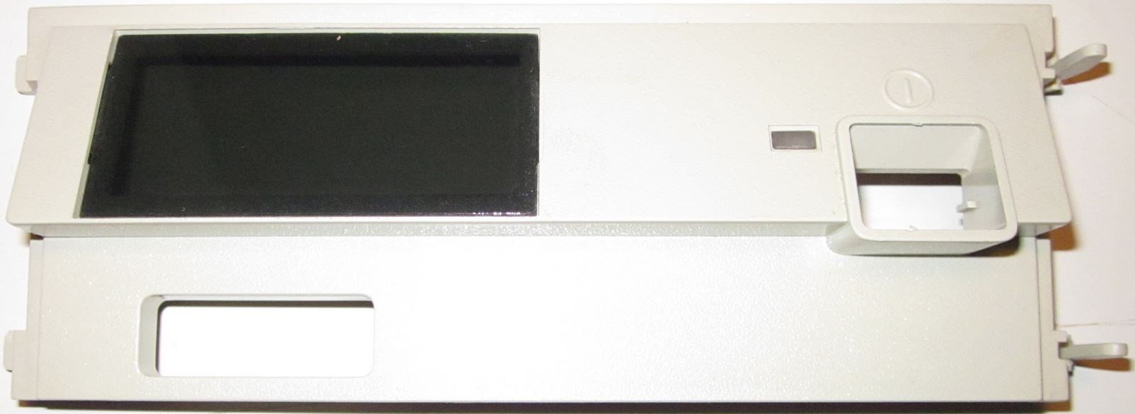
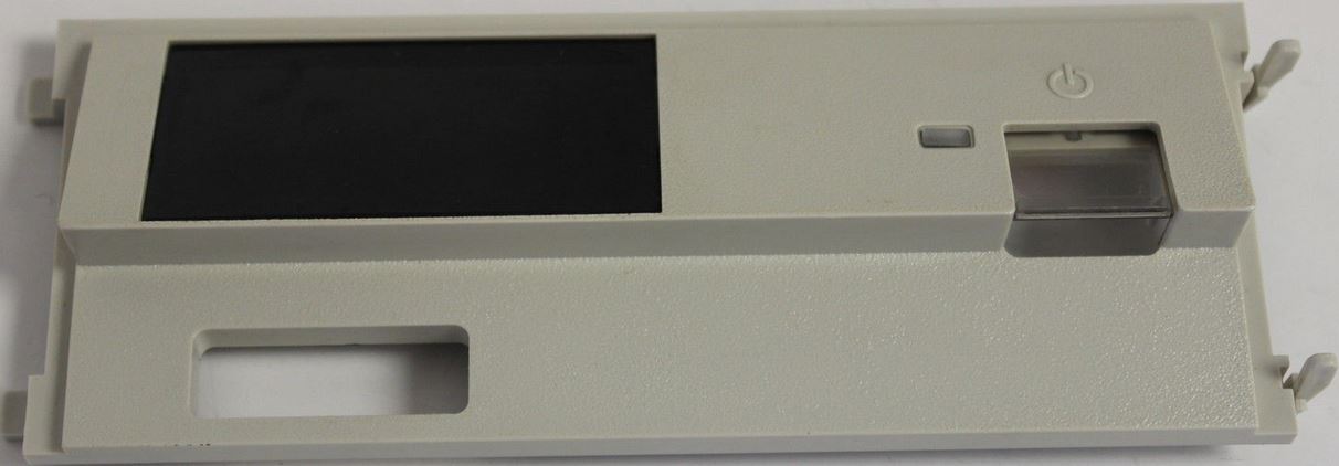
9585, and 9595A Information Panel Bezel (Op Panel
for the rest of us) 8595 Op Panel Bezel, Early Front
33F5408 This is one of the earliest Op Panel bezels, note the
lack of a shutter over the Power Switch button, Power
Good LED, and the raised edge around the button. Note
that the bezel hooks are on the LEFT and the bezel
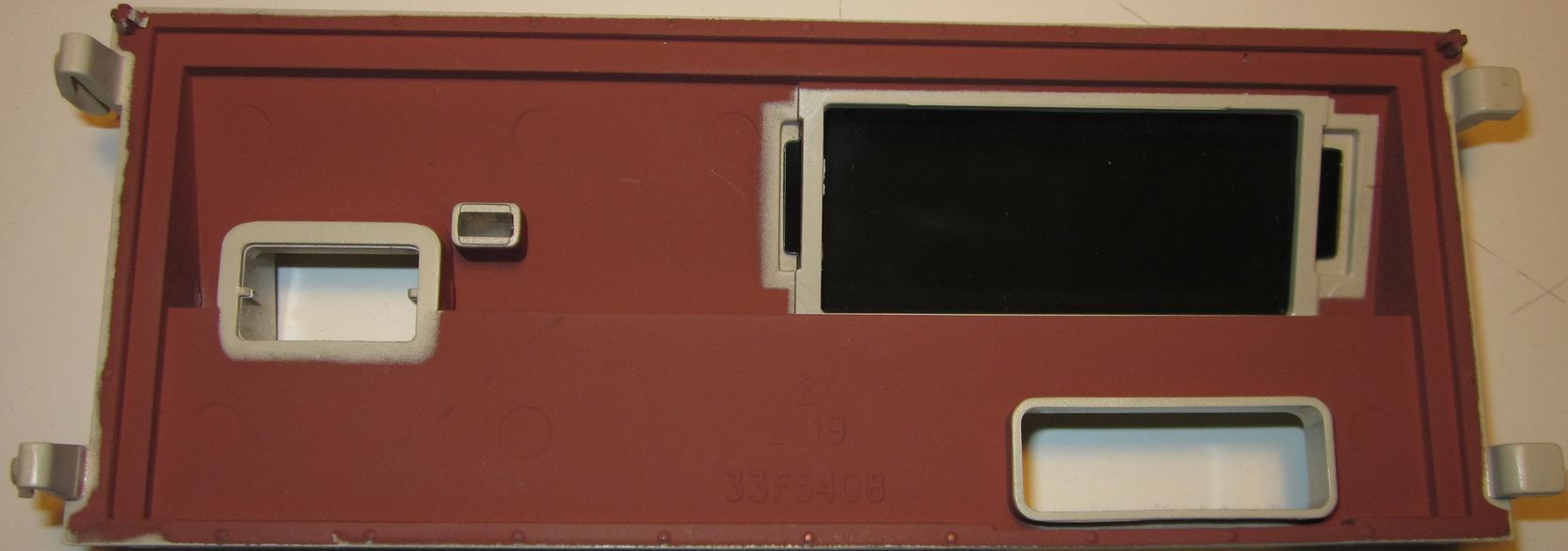
latches are on the RIGHT. (Thanks to Jelte for pix) 8595 Op Panel Bezel, Rear
33F5408 Note the simplicity of this moulded part. See the EMI
shielding? That copper colored coating is replaced on
later bezels by the silvery Enshield (which was probably
cheaper as well...). Note the small locating posts at
the upper corners? They fit into holes in the DASD
retainer. 8595 and 9595 Op Panel Bezel,
Front 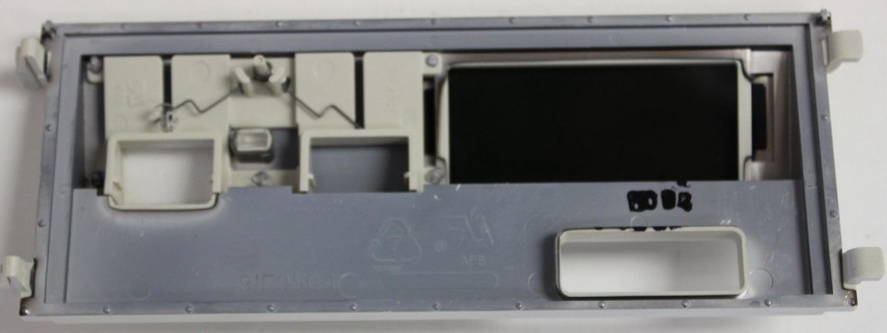 Note the small locating posts at the upper corners? Note the modular assembly, with the white button frame being placed onto the bezel (grey). Peter mentioned that the op panel PCB originally came off an older existing device. Also note the LED window is covered with a darkly shaded piece of plastic. If the plastic window got a little scuffed up, you can push the flexible sheet out, and the tabs will pop out of the frame with no damage. To re-install the window, put one tab in the slot, and bow the sheet a little until the tab re-enters the opposite slot. Note the spring powering the shutter rests on a little hook molded into the shutter. If the shutter haltingly raises, czech to see that the end of the spring is in the hook, not dragging between the front of the hook and the white module. Note the white hook just above and right of the end of the spring. Op Panel Shutter Spring, Richtig (Lorenzo) 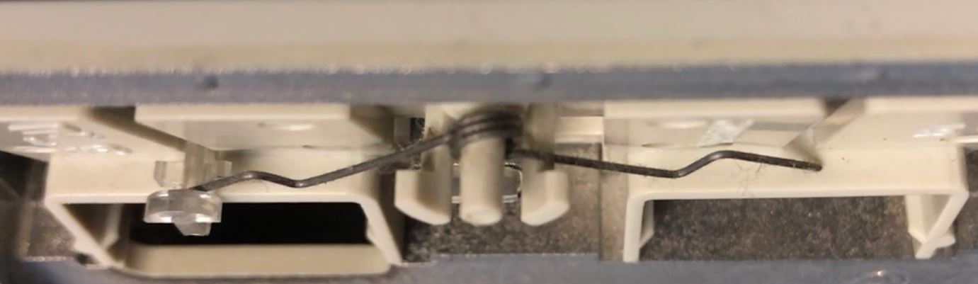 In this daring piece of realism, Lorenzo Mollicone transforms the genre... Er, on the other hand, this clearly shows the shutter spring in the correct position. Op Panel Shutter Spring, Falsh (Lorenzo) 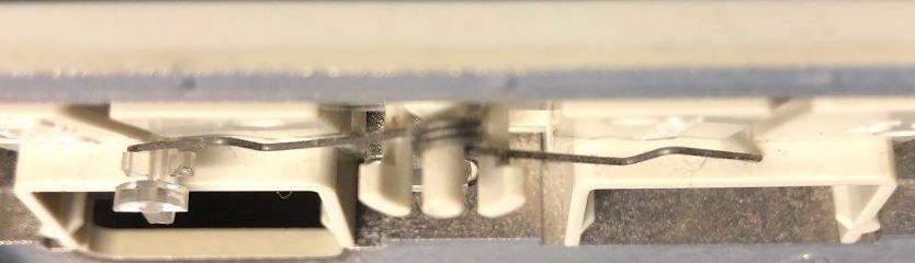 Note the shutter spring is in front of the little "wings" used to guide the shutter up and down. The shutter spring rubs against the subframe, and the shutter no longer moves smoothly. In addition, the shutter is pulled back into the subframe causing resistance as well... 8595 / 9585-N / 9595 Op Panel PCB, Top (Jelte) 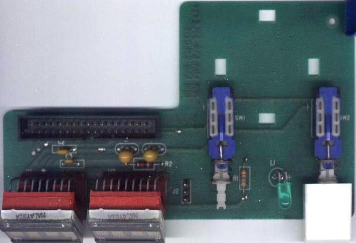 8595 / 9585-N / 9595 Op Panel PCB, Bottom (Jelte) 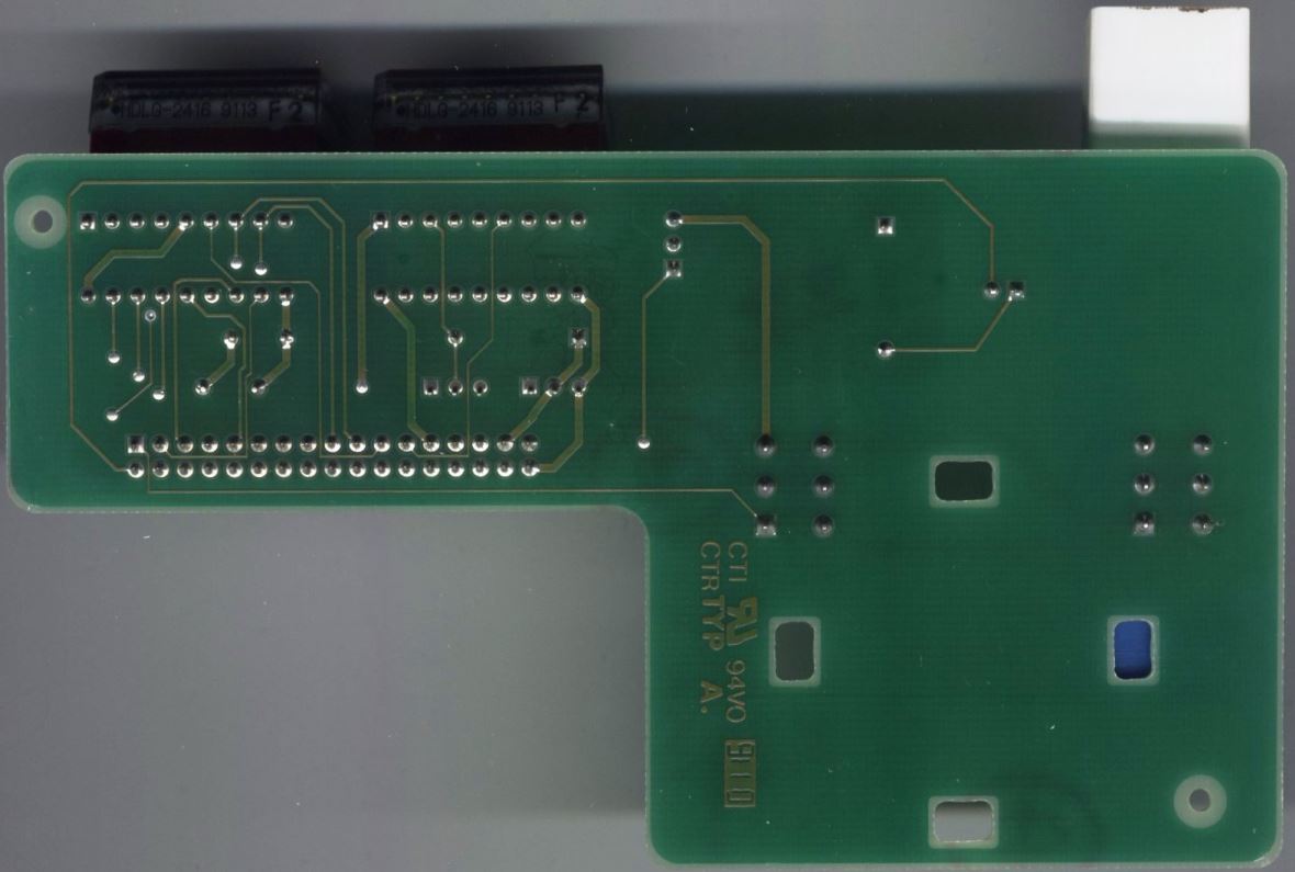 8595 Frame (Jelte) 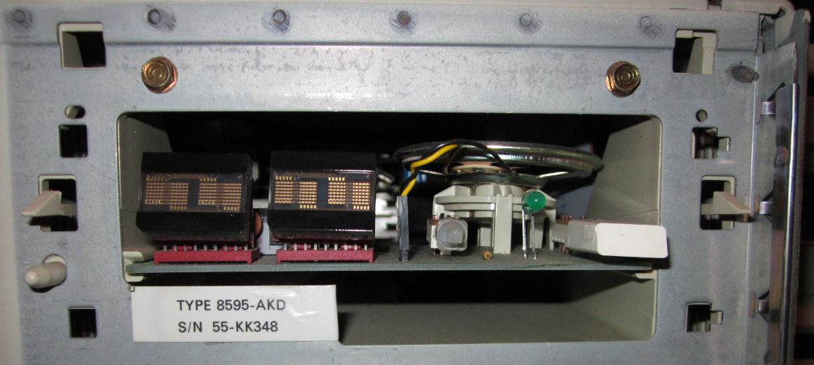 See the rectangular holes on the left for the Op Panel Bezel hooks, while there are similar "T" shaped holes to the right. Note there is only ONE set of small holes for the Op Panel bezel at the top corners. Note the small hole for the alignment pin in the upper left corner is horizontally elongated, while the upper right pin hole next to the latch hole is round. This makes sense, as the hooks on the left are inserted first, and the left pin makes an arc as it enters the hole. The rightmost pin is near perpendicular as it enters the hole near the latch. 9595 Single Serial Frame (Lorenzo) 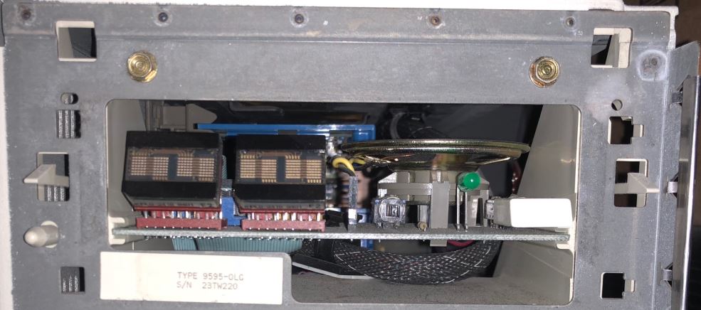 Same as the -AKD, I would surmise the bezel mounting holes changed with the 9585 (K/N?) and 9595A (Dual Serial/Parallel) models. Note that the hook /latch holes are slightly inward from center. Maybe because it was better to not have the drive retainer hooks in-line with the bezel fasteners? Dunno. 9585 Op Panel Bezel, Front 41G9550 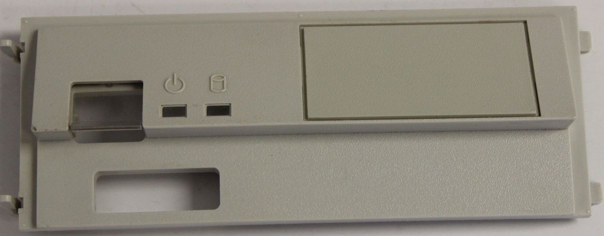 This bezel has a shuttered Power Switch Button, a Power Good LED, a HDD Activity LED, but the Information Panel window has a opaque plastic insert. Note the bezel latches are on the LEFT and the bezel hooks are on the RIGHT. 9585 Op Panel Bezel, Rear 41G9550 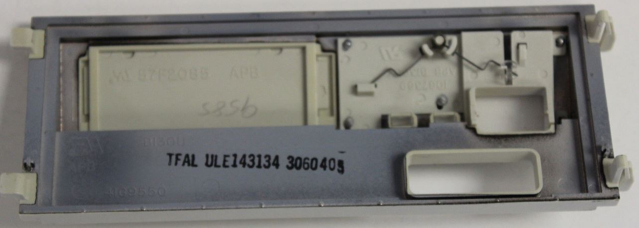 Note the small locating posts have been moved from the upper corners to just above the lower hook / latch? Note that the Information Panel window insert (57F2085) has the same tab arrangement as those for LED displays. The power button frame has lost the well for a second push button, and a second LED light pipe has been added. Note the spring powering the shutter rests on a little hook molded into the shutter. If the shutter haltingly raises, czech to see that the end of the spring is in the hook, not dragging between the front of the hook and the white module. Note the white hook just above and right of the end of the spring. To remove any spring tension from the shutter, place the end of the spring into the hook. 9585-X Op Panel PCB, Top FRU 61F3736 [David Beem] 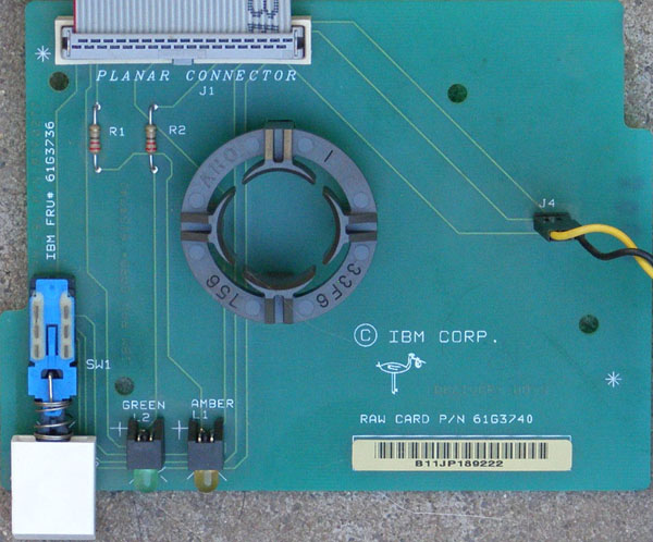 9585-X Op Panel PCB, Bottom FRU 61F3736 [David Beem] 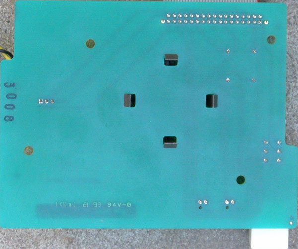 9595A Op Panel Bezel, Front 41G9550 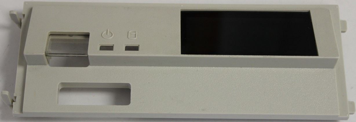 This bezel has a shuttered Power Switch Button, a Power Good LED, a HDD Activity LED, but the Information Panel window has a darkly shaded piece of plastic. Note the bezel latches are on the LEFT and the bezel hooks are on the RIGHT. The 9585 and 9595A use the same bezel. 9595A Op Panel Bezel, Rear 41G9550 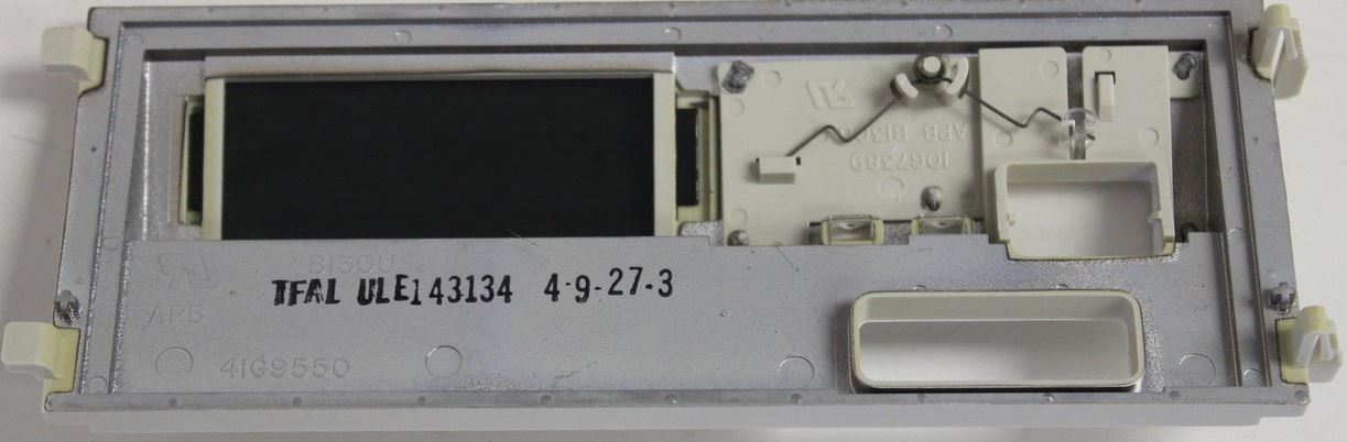 Note that the Information Panel window insert has the same tab arrangement as those for LED displays. The power button frame has lost the well for a second push button, and a second LED light pipe has been added. Note the spring powering the shutter rests on a little hook molded into the shutter. If the shutter haltingly raises, czech to see that the end of the spring is in the hook, not dragging between the front of the hook and the white module. Note the white hook just above and right of the end of the spring. To remove any spring tension from the shutter, place the end of the spring into the hook. 9585-K/N / 9595A Op Panel PCB, Top FRU 92F0259 (Jelte) 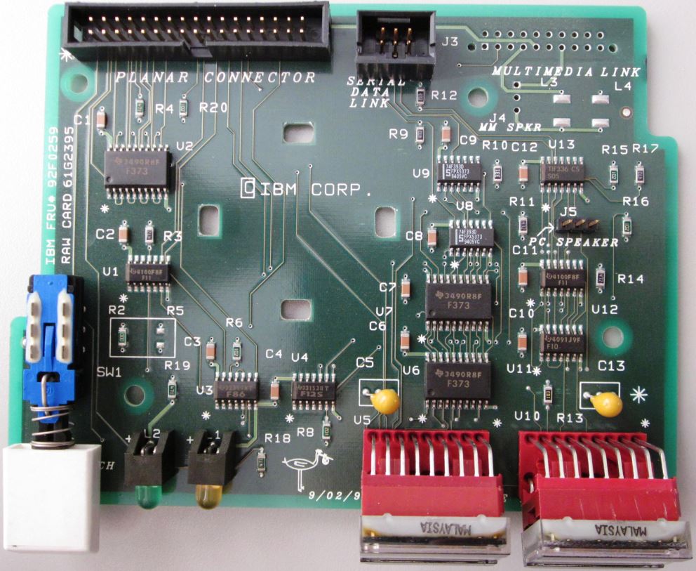 9585-K/N / 9595A Op Panel PCB, Bottom FRU 92F0259 (Jelte) 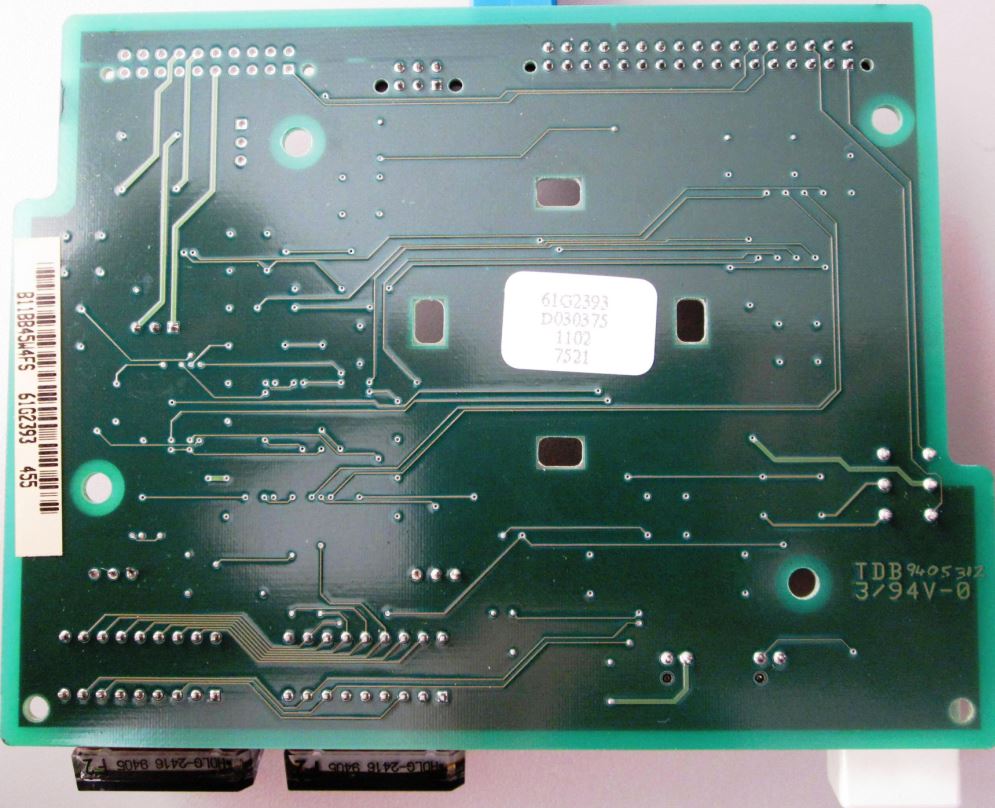 9585 and 9595A Frame (Jelte) 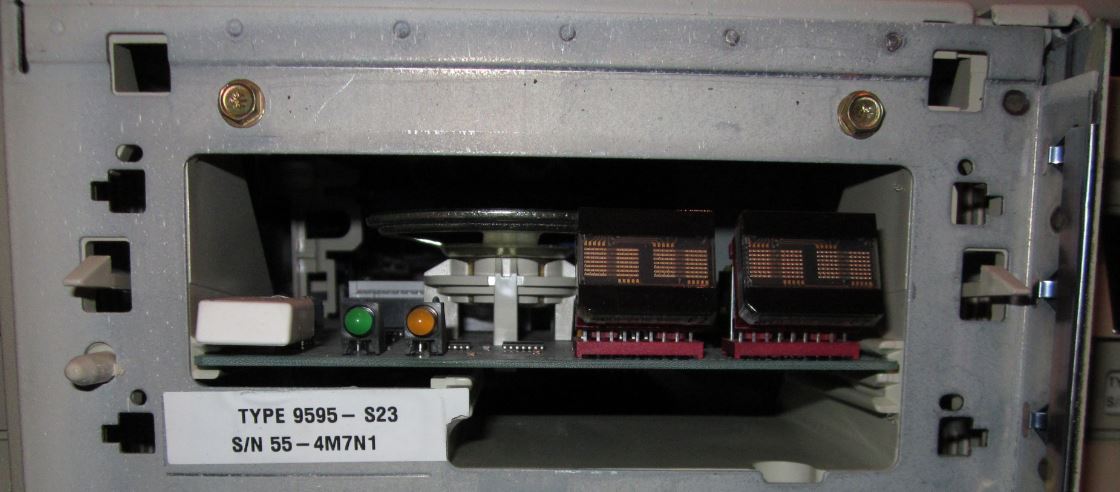 See that the hook -AND- latch >BOTH< use a "T" hole? Note there are TWO sets of small holes for the Op Panel bezel pins, at the top corners -AND- above the bottom hook / latch holes. I suppose you could use one LED bezels on 8595 >AND< 95A frames... Note the elongated hole for the top posts is on the left, and the elongated hole for the bottom posts is on the right. What is the dual card guide doing here? See the Op Panel board is in the upper card guide, and the narrower bottom guides are empty. Note the notch in the frame in the lower right (below right 4 character LED), and the semi-circular relief in the plastic DASD Support Structure... Almost resembles a relief for a thumb wheel... Mounting Hardware 
Drives come in a variety of heights. You can install half-high drives that are less than 41.3 mm (1.6 in.) high in any of the bays. Drives that are greater than 41.3 mm (1.6 in.) high (full-high) can be installed in bay C or bay D. Bays C and D can each hold two half-high drives or one full-high drive. Slide
- Mount floppy drive sized devices in Bays A and B
(floppy, tape, or PCMCIA)
Cover plates (sometimes called bezels) cover the front
of each installed drive. If you install a drive that
uses removable media (diskette, tape, optical disc, or
CD), you will need to change the cover plate. Tape Drive Bezel 34F2721 34F2719 Installing Floppy Drives 
Install the diskette drive in bay A or B: Note: The figures that accompany these steps show the installation occurring in bay A. These instructions also apply to bay B. a. If a flat cable is folded inside bay A, unfold it and route it along the back of the bays. b. Position the drive so the connector is facing the rear of the server. c. Align the drive with the guides on the bottom of the bay. d. Slide the drive into the bay until it stops.
3.5" Floppy Drive Slide 64F0156 Remove Rail Guide From Storage Tray 
Pull up on the tab (1) on the back of the tray and pull out the rail guides stored on the bottom of the tray. Storage Tray 84F8075 Insert Rail Guide
5.25" Drive Rail Dimensions 
I measured this from a single RAID bay. HD Mounting Tray  85 P/N 85F0013 My 9595s are stamped 10G4769. NOTE: The drive may
be installed in the tray with the mounting screw flange
pointed down (as pictured) or pointed up. This is
helpful if you have a mix of 1.6" and 1" drives to
install. The 3510, 56, 57, 76, 77, 85, and 95 all use the same
HD Mounting Tray. Hard Drives can be mounted with the mounting screw
frame on the lower side, or the mounting screw frame
above the rails. |
 a. Insert tabs at bottom of drive
retainer into groove at bottom of server.
a. Insert tabs at bottom of drive
retainer into groove at bottom of server.