|
@8DF0.ADF - IBM Image Adapter/A @8DF1.ADF - IBM Image/A and Printer/Scanner Option @8DF2.ADF - DSS and sub card 2 @8DF3.ADF - DSS and sub card 3 @8DF4.ADF - IBM Image Adapter/A 3MB @8DF5.ADF - IBM Image/A with Printer/Scanner Option imageopt.exe PS/2 Image Adapter/A options diskette, version 1.04 Ver 1.02 + correct Arbitration conflict , 1.03 corrects OS/2 2.1 install iaopt211.exe Image/A & Image-I Opt Dsk (incl 76/77 ) Combined I/A and I-I/A, no idea of version, probably later than 1.04? BIOS version 3.00 14-06-90 ST M27C256B-15 45F3367 The last version seems to be 14/04/92. Unsure if there is a relationship between PCBs? 189-037 IBM PS/2 Image Adapter/A and Related Features 190-108 Image Adapter/A 1MB, 3MB and 3MB 6091 S71G-3708 IBM PS/2 Image / Image-I Adapter/A Technical Reference 71G3708 Image Adapter/A Hardware Maintenance Library ('90) S15F-2240 15F2240 Image Adapter/A Technical Reference ('90) S15F-2162 15F2162 COMPEURO 89 Proceedings VLSI and Computer Peripherals. May 8 1989 to May 12 1989 Hamburg, West Germany The IBM Image Adapter/A by R.J. Bowater A VLSI display controller and processor by Adrian Gay A 1-micron CMOS 128 MHz video Serialiser, palette, and DAC chip by Martin J Chesters The VLSI 'silicon compiler' design process by R.M.P. West Drivers Painful Probulation:
WBST:
Image Adapter/A Image Adapter/A DCP and DSC Functional Islands Printer/Scanner Option Image HDD15 Pinout Example WIN.INI Displayable Modes Installing Data Files Using Non-Standard Displays Display ID Numbers Monitors Supported (DISPFILE.0xx) ADF Sections Image Adapter/A 
TMS44C256-12N Enhanced page mode operation with CAS [-] before RAS [-] refresh KM44C256AP-10 [-nP is DIP version] MT4C4256-8 U43 -MIGHT- be a Hitachi HD63484 Advanced CRT Controller (ACRTC) datasheet HD63484 ACRTC Advanced CRT Controller User's Manual U10-13 / U14-17 Base 1MB VRAM Display Memory U18-21 / U22-25 Optional 1MB VRAM Display Memory U2-9 Optional 1MB DRAM [Work Area] U26-29 512KB Instruction DRAM U31 188666 / RISC Video and I/O Processor (Display Controller and Processor (DCP) ) Cotswold II ? U33 Serializer / Palette / DAC [SPD] U43 Display Support Chip [DS] Differences Between 07Fnnnn and 06G822n The '90 07F2511 is littered with decoupling caps... It has a 4.0 MHz crystal above U33, and a 4.0 MHz osc to the lower left of J1. U33 is 9019 and U31 is 9034. BIOS is 17/10/90. All logic is through-hole but all memory is through-hole DIPs or socketed DIPs/ZIPs. The '92 06G8224 [35G4719] only has a 4.00000 MHz osc above U33 and NO XTAL. The glut of decoupling caps are gone, much smaller SMD logic chips have replaced more than a third of the logic, but all memory is still through-hole DIPs or socketed DIPs/ZIPs. U33 is 9226 and U31 is 9223. BIOS is 15/06/92. The 07Fnnnn versions will positively blow chunks with an M complex. The 06G8224 will work with the M complex... Huh, I see a 35G4715 / 06G8224, with a DSC of 9106, yet I see other 06G822x with chip dates of '92... Can't prove it, but this makes sense if the 8221, 8222, and 8223 are the same board but with / without options disk. I wonder if 8224 has the 1.04 options disk... Installation of IBM PS/2 IA/A in 32-bit system slots is restricted to those without matched memory extension. DSC Date Code While comparing the 07 and 06 variants of the Image /A, I was stumped on deciphering the date code of the DSC, U43.
Look at the eleven digit code on the third line. The first digit is the year digit starting in 1990. The second and third digits are the week. So, "020" Means 1990, week 20. 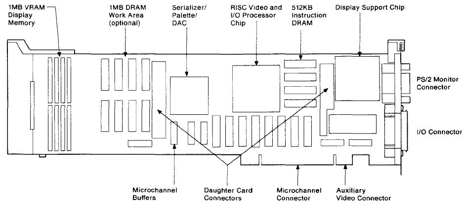 Image /A Block Diagram 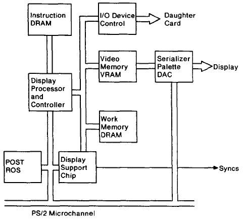 The Display Support Chip A small gate-array VLSI chip providing synchronization and timing pulse generation for the display and Image Adapter card. Image Adapter/A DCP and DSC Functional Islands 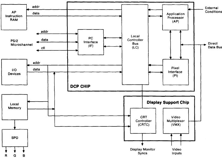 Image /A Display Processor Block 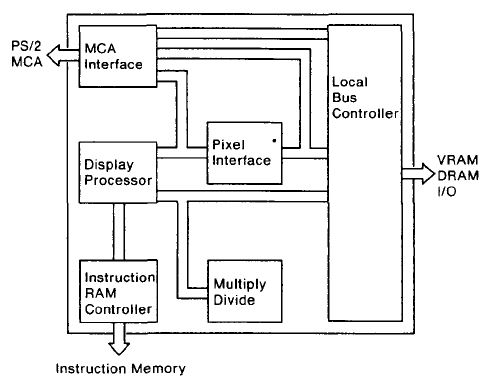 Image/A Serializer / Palette / DAC Block [SPD] 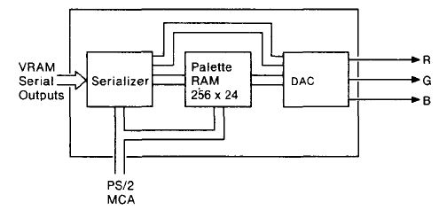 The Serializer/Palette/DAC circuit types integrated on a single chip: 1. High speed static RAM (8ns access) 2. Logic (6000 cells) 3. Digital-to-Analogue convertors, custom designed 4. Phase-Locked-Loop and Voltage-Controlled-Oscillators The SPD chip provides all the function of the INMOS GI71 component used on PS/2 planars and in the IBM 8514/A display adapter. However, the SPD has improved flexibility and function over the IBM VGA and 8514A: INMOS G171 compatible palette & DAC Colour comparators for diagnostic verification of DAC outputs 32 bit to 8 bit serializer Cost-reduced DAC current and comparator voltage reference sources Clocks and dividers for PS/2 monitors of 25.175, 28.321, & 44.90 MHz. Additional function and flexibility is provided: 256 by 24 palette with 8 bit DACs Support for a video data word width of 8, 16 and 32 bits formatted as 1 , 2, 4, 8 and 16 bpp. Generation of video logic and shift clocks for the CRTC and video RAMS Differential current outputs. From what little I see, 16bpp is "palette bypass" [Direct Color] like the original XGA. Image Adapter/A Versions 1. Image Adapter/A 1MB - 1MB VRAM. 2. Image Adapter/A 3MB - 2MB VRAM and 1MB DRAM. 3. Image Adapter/A 3MB 6091 - Image Adapter/A 3MB with cable for IBM 6091 - 019. NOTE: There is no 2MB version of the Image Adapter/A. 2MB VRAM / 0MB DRAM - OR - 1MB VRAM / 1MB DRAM? Downlevel: Same PCB, different memory amounts P/N 07F4401, 07F2481, 07F2508 P/N 07F4401 - Replaced by P/N07F2508 P/N 07F2481 - Replaced by P/N06G8224 + P/N75X5894 (8 VRAMS) P/N 07F2508 - Replaced by P/N06G8221 Current: Same PCB, different memory amounts P/N 06G8224 Image Adapter/A 1MB CURRENT LEVEL P/N 06G8221 - Same as P/N 06G8223 w/o Image Adapter/A Ver 1.03 Option Disk. P/N 06G8221 - Replaced by 06G8223 P/N 06G8223 - Replaced by 06G8224 (CONTAINS 1.03 Option Disk) 1 MByte FRU ==> 06G8221 3 MByte FRU ==> 06G8222 8590/95 "M" System Hang with Image Adapter/A installed H101665 A CP 40 (Stage 1 Video Test) POST Hang Condition Will Happen on an 8590 / 8595 0MF or 0MT (50MHZ complex) if an early version Image Adapter/A is installed. 8590 / 8590 "M" class systems must have Image Adapter/A FRU P/N 06G8224 (MKTing Option 35G4712, 35G4713, or 35G4714). The Following Image Adapter/A will not work in the 50 MHZ 8590 and 8595 FRU P/N 06G8221, 06G8223, 07F2481 and 07F2508 Printer/Scanner
Daughtercard FRU
07F4403 (From
William Walsh HERE)
Z85C3010PSC CMOS SCC (serial communications controller) 10MHz Datasheet 85C30 Optimized for non-Multiplexed Bus Microprocessors Using Image
Adapter/A with 4216-020 Personal Page Printer
1. This is only applicable for the "Image Adapter /A" - not the Image-I-Adapter. 2. You need the "Printer / Scanner Feature Card" FRU 07F4403 and the "Printer / Scanner Y-Cable" FRU 07F4417. Probably the "Memory Module DRAM" (Kit) 07F44407. The Y-cable connects to the IBM 3117 Scanner on the one side and to the 4216-020 "Raw Engine" on the other port. However: the driver support was rather poor (Win 3.0 / 3.1 and OS/2 up to 2.0 only IIRC). Have seen this combo at a customer once (back in 1991 or so) but never worked with it nor serviced it. Peter
in Germany Image Adapter/A Part Numbers 1-MB MKT P/N 35G4715 3-MB MKT P/N 35G4716 3-MB + 6091-Cable MKT P/N 35G4717 9527 Cable MKT P/N 95G9906 9521 Cable MKT P/N 95G9907 The Image Adapter/A is capable
of driving displays up to 128 MHz, with a maximum
resolution of 1600x1200 pels. The Driver output
impedance for video signals is 75 ohms. The sync lines
of the adapter are TTL levels driven by 4ma drivers, so
termination should be at 750 ohms (minimum) It contains a 32
bit 8.5 MIP display processor, a 128 MHz serializer,
video palette, digital to analog converters and a CRT
controller. Memory consists of 1MB VRAM (U10-17), optional 1MB of VRAM (U18-25), 512KB of instruction RAM (U26-29) and 1MB DRAM Memory Expansion (U2-9). Printer/Scanner Option
(#1632) is available allowing direct attachment of
: Image Adapter/A Memory
Configurations
Image Adapter/A Memory
Modules: FRU P/N QTY
DESCRIPTION COMMENTS The three versions of
the Image Adapter/A support IBM analog displays equipped
with a 15-pin direct-drive analog interface There seems to be three incompatible systems, the
8557SX (DMA?), the 8573-P70 (video slot steals a line
for dimming the plasma), and the 8570-A21 (unknown if
486 based -Bxx also affected). 6019-019 Display Cable This cable is included with the Image Adapter/A 3MB 6019. The cable must be ordered separately for all others Image Adapter/A Options
Image Adapter/A 15-pin Analog Video Connector 
Example WIN.INI An example set of options in the WIN.INI file looks like: [Image Adapter/A] Version Version of Image Adapter/A Win3.1 Display Driver . Resolution X and Y dimensions (in pixels) of the display mode required. See HERE for a list of valid modes. If an invalid mode is specified, the driver reverts to its default (the highest resolution available on the display attached). BitsPerPixel Specified as 1, 2, 4, 8 or 16. Note that some of the higher bits per pixel are invalid in some of the Image Adapter/A memory configurations. If an invalid bits per pixel is specified, the driver reverts to its default (the highest bits per pixel available (up to 8) at the selected resolution). PaletteManager At 1, 2 and 4 bits per pixel, the palette is fixed to 2, 4, and 16 colors respectively. The Palette Manager options do not apply and are ignored. Dithering is enabled to approximate colors that are not in the palette. At 16 bits per pixel, the adapter is in direct color mode and there is no palette, the Palette Manager options do not apply and are ignored. Dithering is disabled. Three PaletteManager options, at 8 bits per pixel YES
Palette Manager enabled NO
Palette
Manager disabled GRAY
Gray scale palette If you need to switch this option on or off see "Switching the Palette Manager On and Off". MemoryUsage Reserved for special applications designed to run only on the Image Adapter/A. Unless you are using one of these special applications this option should always be set to Maximum. DualScreen Only applies when you have two displays attached to your system. For example, a VGA display attached to the standard VGA port of the system unit and a high resolution display attached to the Image Adapter/A. NO The display attached to the Image Adapter/A will always be used as the main display for running Windows applications and full screen VGA applications. When running full screen VGA applications both displays will be showing the same results. This is the default setting. YES During a Windows session the display attached to the Image Adapter/A will be used only for running Windows applications. When running full screen VGA applications (from within the Windows environment) only the VGA display will display the VGA application. Windows applications running in the background on the Windows display will continue to be updated. If you have only one display (attached to the Image Adapter/A), select NO for this option. StretchBlt Whether the driver registers its capability to scale images. YES The display driver will register the StretchBlt capability and image scaling will be preformed by the adapter. This results in a considerable performance improvement. This is the default. NO The display driver doesn't register the StretchBlt capability and the Windows graphics engine simulates the image scaling in software. VirtualScreen X and Y dimensions(in pixels) of the virtual display mode required. The x possible value is 1024,2048, 4096 and y possible value is 1024,2048,3072,4096. See Table 5,6,7 for a list of valid modes. Virtual screen is not supported with only 1MB card. If invalid value is specified, virtual screen is disabled. If you want to disable virtual screen, specify "VirtualScreen=No". Display Modes
The following tables show the display resolutions and
bits per pixel available for the various display and
memory configurations. The numbers represent the bits
per pixel. A blank box means the resolution is not
supported. There is more information, in the READ.ME of
Display support diskette. Refer it for the detail.
Displayable Modes Monitor
Res Maxbpp H-Freq
V-Freq Pix-Freq Int 8514
640x480 16*
31.56 60.12
25.25 N 8508
640x480 8
70.79 67.04
64.00 N 8506 864x1200 8 50.57 40.10 53.00 Y 6091-019
640x480 16*
70.75 67.00
60.00 N 6091-019
640x480 16*
63.06 60.00
55.00 N 8517
640x480 16*
31.56 60.12
25.25 N 1091-051
640x480 I 8
75.47 71.20
64.00 N 6091-016
640x480 8
81.14 76.83
74.00 N 9515
640x480 16*
39.37 75.00
31.50 N 9518 640x480 16* 39.37 75.00 31.50 N 9517
640x480 16*
39.37 75.00
31.50 N * - Windows up to 16bpp, PM/DOS/AIX supports up to
8bpp How to Install Display Data Files to Your System Image Adapter/A version 2.00 or later drivers automatically detect the attached monitor and find correct Display Data File. You can also specify the name of Display Display Data File to be used and its directory. Each driver expects the default directory path to find Display Data File if no special path is specified. The default directories are as follows. DOS
AI :
C:\IMGAIDOS If you wish to specify Display Data File name, please add the option to your system CONFIG.SYS driver statement like the following example. (The case of Windows driver) DEVICE=C:\IBMIAA\IADOSRFS.SYS /DisplayID=49C Where, 49 is decimal value of hex 31 (DISPFILE.031), and 'C' indicates this is a color monitor. If you change 'C' to 'M', driver assumes the attached monitor is a monochrome monitor which has the same timing. If you wish to change Display Data File directory other than default, please add the option like the following example. (The case of OS/2 driver) DEVICE=C:\OS2\IBMIAA\IAOS2RFS.SYS /DisplayPath=E:\DDFPATH You cannot change default Display Data File path in AIX
driver by this option. Please refer to readme file in
each driver diskette for further information about each
driver installation. Using Non-Standard Displays The Image Adapter/A can connect to any display that is compatible with the IBM Displays, 8503, 8506, 8507, 8508, 8512, 8513, 8514, 8515 and 6091 19". To enable other displays to operate correctly you may need to override the display ID that is returned by the display. The display ID override is a command line option that
should be placed after the DEVICE=IADOSRFS.SYS line in
your CONFIG.SYS. For example to override the display ID
to 8 for a color display the line would look like:- Table 9 lists the different ID's that should be used for the various possible modes. Note that you still need to specify the correct resolution in the WIN.INI file.
Note:- IL refers to interlaced and NI refers to
non-interlaced. Monitors Supported Image Adapter/A and Image-I Adapter/A Display Support diskette 2.10 These files are used to install version 2.00 or later level of Image Adapter/A and device drivers to your system. Each file has a information table for the following monitor. DISPFILE.000
: No monitor AdapterID 08DF4h "IBM Image Adapter/A" (with 3MB) DMA Arbitration Level
Fairness On/Off Adapter I/O Addressing
Adapter Memory Location
Extended Memory Window
NOTE: WBST cautions: Extended Memory window can only be enabled if, at most <=14MB is installed in the system. A slightly important caveat. This becomes a concern in later systems. Interrupt Level |
|||||||||||||||||||||||||||||||||||||||||||||||||||||||||||||||||||||||||||||||||||||||||||||||||||||||||||||||