|
192-297 IBM PS/2 Server 295 Preinstalled Software 193-097 IBM PS/2 Server 195 (8600-003) 193-098 IBM PS/2 Server 295 Enhancements (8600-001 AND -002) 193-099 Netware Software for PS/2 Server 195/295 193-215 IBM OS/2 2.1 Support for IBM PS/2 Server 195/295 193-388 IBM Internal 8MM Tape Drive for PS/2 Server 195/295 292-302 IBM Maximum Availability and Support System/2 IBM Multi Processing Extensions/2 IBM Orthogonal RAID-5 Disk Array/2 195295fm.exe
Server 195/295 Field Maint. Test 2.0 S1 - Select Applications Processor (AP) or File Processor (FP) CPU 1 (FP) connects to four-slot MC (Primarily NICs) CPU 0 (AP) connects to eight-slot MC (Primarily system - tape, fax, 3270, etc...) For a dual CPU system, CPU 1 AP/ FP switch should be for FP. For a single CPU system, it does not matter how the AP / FP switch is positioned. The 4 and 8 slot MCA planar is ONE board that plugs into the IPB backplane. You cannot change which CPU Slot connects to which set of MCA slots. The 195 comes with this 4 / 8 slot planar installed, so when you get another CPU Board, you just plug it into the IPB card cage. In the dual processor 295, the OS/2 HPFS runs on the File Processor, and OS/2 LAN Server and the application(s) run on the Application Processor. The OS/2 kernel and the interprocessor code run on both processors. IPB CPU Card 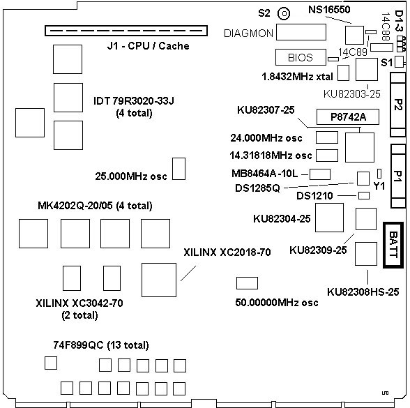
Clear CPU Board CMOS Right next to the watch xtal are two loops, in this case TP2 and TP3. Procedure: Remove CPU card from server. Momentarily short TP2 and TP3, shorting out power to CMOS and erasing settings. Intel 82311 Peripheral Family NOTE: "Support" does NOT mean the primary controller! 82303 Local Channel Support Chip (LIO) Bus interface MCA / Peripheral Parallel Port Card Setup Port (96H) Motherboard Setup Support 82304 Local Channel Support Chip (LIO) Bus Interface & Control System Timers FDD Support Interrupt Control RTC & Configuration RAM Support VGA Support & VGA Setup Enable / Disable Serial & Parallel Port Support Math-Co Support KB and Mouse Support System Status & Control Functions 82307 DMA Controller / Central Arbiter chip DMA Function MC Arbitration MC Refresh Address Generation / Cycling (82309 makes Refresh Request) Address Decoder (for 8259s) 82308 Micro Channel Bus Controller State Machine Data Transfer Reset Detect I/O Support Cache Support Cache Flush Snoop Strobe Hardware Enforced I/O Recover 82309 Address Bus Controller Ports and Registers Refresh Timer DRAM / BIOS EPROM Address Mapping DRAM Controller Intel486TM DX CPU-Cache Module 82495DX / 82490DX Presentation on CPU-Cache Module CPU Board Diagnostic LED Codes The processor module starts up,
displaying these codes, in
the order seven through zero.
X = OFF, O = ON EBIOS is a Phoenix Technologies product. Parallel port has a security dongle attached. Rainbow Technologies Sentinel Pro, model 4BNZBH-B Sentinel Pro drivers, ver 5.38 DOS, OS2, Win 3.1, Win 9x, NT WBST said: The only reference to "protection keys" appears to apply solely to IBM's Orthogonal RAID-5 Disk Array/2. Presumably these keys are to ensure the software is licensed to operate on those CPU boards. The details aren't exactly very clear. Announcement Letter 292-302 o IBM Orthogonal RAID-5 Disk Array/2 - Hardware security keys must be installed in each system processor. Sentinel Pro FAQ Q: The SentinelPro is a non-programmable key, how is my key different from anyone else's? A: All production units have unique Developer IDs assigned to them. Each Developer will also get their own algorithm. Q:How do I know what response I should expect when querying my key? A: The Proeval utility, in the tools subdirectory of your SentinelPro software installation, can help determine the responses your key will return to a given query. You can also generate a simple program that queries and stores the responses in a query/response table. Q:Query returns the same response when the key is absent as it does when the key is connected? A: You may not have initiated the program to communicate to the key. There are two common configurations which you need to keep in mind when you initially query the Pro: Parallel Port Setting, and Family Code setting. The default for these two settings are LPT1 and "BH". If you are using a key on a port other than LPT1, you need to specify this in your code. If you are using any family code other than "BH", you need to make sure that you have set up the family code prior to the first query/response check. Q: How do I set up the Family Code? A:Whenever you send in two characters as a query string, it is a command to the driver, and not a true query. To change set up the Family Code for your key, you need to query "3x" to set up the first digit, and "4x" to setup up the second digit ("x" represents the each character of the family code.) For example, if you have a family code of BC, you will set up your code with the following: SSQUERY("3B"); SSQUERY("4C"); Note: The syntax used to pass the query string is slightly different for each high-level language. Q: How do I know what family code has been assigned to my key? A:Look on the plastic case of your key. There will be a string of digits and characters that will start with RB-XXXXBH-B. You would look at the last three characters of this key. The two characters before the second dash is the family code. The character after the second dash says that it responds on the BUSY line. Q: Can SentinelPro keys be cascaded with other SentinelPro keys? A: Yes. Up to five SentinelPro keys can be attached to the same parallel port at the same time allowing protection for multiple applications. Cascaded SentinelPro keys must have different family codes. Q:Can SentinelPro keys be cascaded with a non-Rainbow key? A:If you must attach a non-Rainbow key to the same port, attach the SentinelPro key directly to the port, then attach the other device to the Sentinel Pro. Looks as if the IP board is the same for a DX33 and DX50. The daughtercard connects with a (Jim) Beam type connector, instead of the pins used in the 8570-Bxx. Intel486 DX CPU-Cache Module 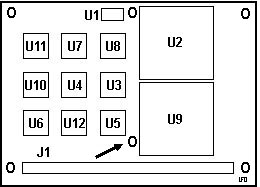
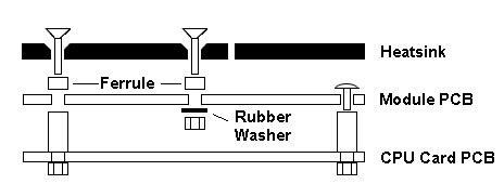 Intelligent CPU / Cache Module Removal If you either disassembled it for fun, or if you got a 486DX-50 module to replace a 486DX-33 module, you can save yourself some pain... DO NOT try to remove the heatsink over the CPU and cache controller. The adhesive is very good... There are two hex standoffs on the right side of the CPU / Cache module. You must only remove the nut on the reverse side of the IPB board. There is no easy way to tighten the screws holding the module PCB to the hex standoff as they are under the CPU heatsink! Unscrew the phillips screws by "J1" (lower left corner), upper left (by U11) and center top (to right of U1). WARNING! Each screw runs through a ferrule (spacer) so that the heatsink is held snugly, but not bowed down over the cache chips. These ferrules are loose! Disassemble the module on a workbench so when something small falls off, you can find it. I didn't mention loosening the screw to the lower right corner of U5 (called out with the arrow). Leave this alone until after you pull the CPU/Cache Module up off of J1. You CANNOT reach the nut below the module until the module has been detached from the CPU Board!!! NOTE: The phillips screw to the lower right of U5 does not thread into a hex standoff. Instead, there is a rubber washer that is put on the screw below the module PCB and the nut is then tightened up against the rubber washer. Do not fasten the no-hex screw without the washer.... Re-Assembly of Heatsink onto CPU-Cache Module The cache chip heatsink on the left is held in with those countersunk head phillips screws, and the heatsink rests on four small ferrules that are loose. BUT you need to tighten up that screw between U5 and J1 (using a rubber washer below the daughtercard) before mounting the daughtercard, because that captive tooth washer nut is TOTALLY inaccessible once you plug the cache card on.... TOTALLY. Outline of Intel486 DX CPU-Cache Module 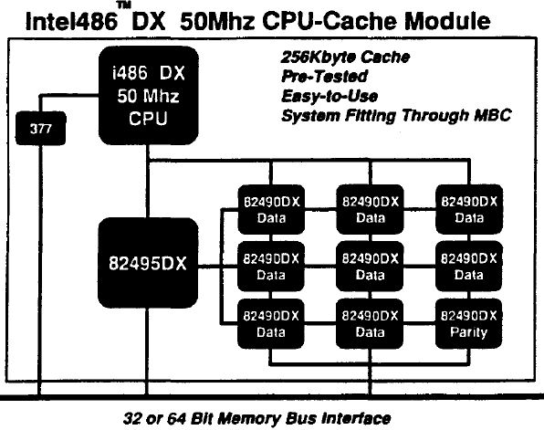 One 377 latch, a 486DX-50, an 82495DX cache controller, 8x32KB 82490DX cache modules (Data), 1x32KB 82490DX cache module (Parity). Module outline is stylized... CPU-Cache Module without Heatsinks (from HERE) 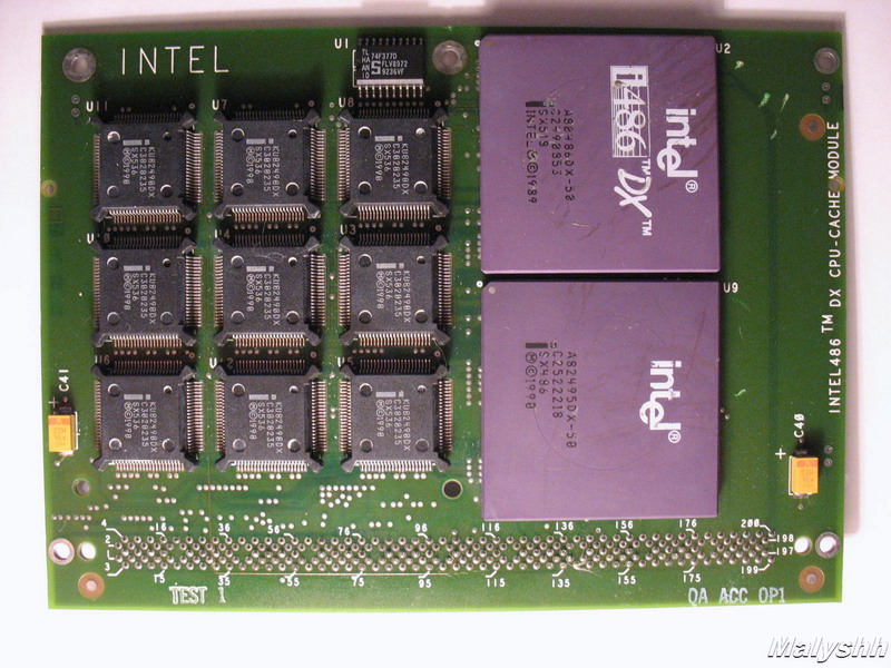 Processor: Each processor board has a switch on the mounting
bracket, AP or FP. 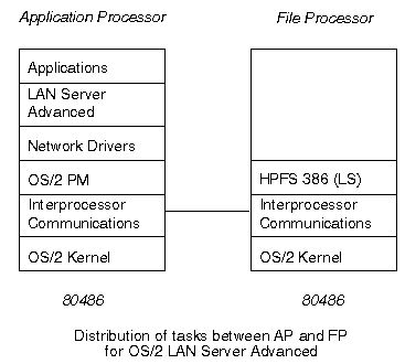
Each processor board contains a 486DX processor, along
with a Level 2 memory cache, and the attachment to the
Micro Channel. There are two Micro Channels, one with
four slots, and the other with eight slots. The
processor in slot 0 is always connected to the
eight-slot Micro Channel, and the processor in slot 1 is
always connected to the four-slot Micro Channel.  Configuring the Server 295 for
multiprocessor or uniprocessor mode is done using the
utility MPSETUP, which is also used for installing Multi
Processing Extensions/2 and for allocating memory to the
AP and FP processors, and the HPFS cache.
When configured for multi-processor
mode, changes are made to the CONFIG.SYS file, and a new
CONFIG.FP file is created for the FP processor. However,
the utility MPSETUP should always be used to switch
between uni-processor and multi-processor modes. It is
wise to always return to uni-processor mode before
altering the CONFIG.SYS file or upgrading the operating
system.
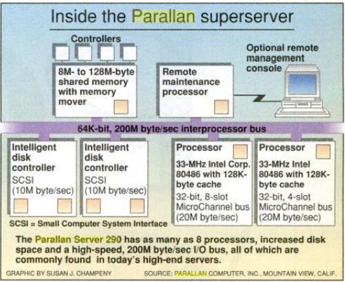
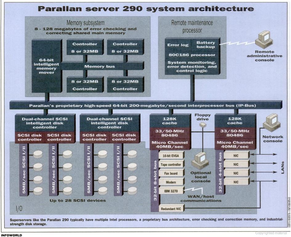
 Bus Architecture: Inside the Parallan Super
Server Parallan Server 290
Architecture |