|
The 8590 and 9590 uses the same reference and diagnostics disks used by the 8595 / 9595 systems. for a list by processor complex, go HERE SHS15F2247.boo
IBM
PS/2 Model 90 XP 486 HMS (Requires IBM Bookreader)
Model 90 HMM Extract
Model 90 information from HMM 190-176 IBM Personal
System/2 Model 90 XP 486 (8590-0J5, -0J9 AND -0KD) Model 90 Pages: Model 90 Planar (All drivers, refdisk/diags, planar inforation] Model 90 Power Type 0 and DBA-ESDI Success! Model 90 Front View Model 90 Planar Base Fan (fan in front of complex) Why was Model 90 Introduced? DBA-ESDI Boot Support with the Type 0 "Model" 90 Careful cable routing and component selection "Clean" CDROM Attachment J1 on 90 Planar DBA Artifact on 8590s (Yes, they DO work!) Mounting Model 90 Vertically 64K Colors Supported under W98SE Video Ram Video RAM Installation 8590 and 9590 Planar Differences 9590 Floppy Controller Model 90 Floppy Cable Adapting 34 Pin Clone Cable to 40 Pin Port Floppy Sleds Three Floppy Experience * Marked 2.88MB Floppy Drives on 8590s Hard Drive Slides Model 90 Drive Slide Conductive Coating Electromagnetic Shields EMC Shields for A, B, C, and D Bays Adapter Card-Guide Assembly Combined Fan / Card Guide thingy Memory Riser Orienting SIMMs on Riser Loading SIMMs 8590 Memory Parity Errors / Configuration H095511 ECA084 Model 90 Memory Riser Card Error 201 Plastic SIMM Holders Riser Support Bracket Memory Expansion Boards Front view  Badge- Grey, XGA. Blue, XGA-2 Adapter originally installed (Blue = ISO compliant). Floppy 1.44MB (8590) or 2.88MB (9590) 5.25" Bay Outer rails are for a 5.25" drive. The left and center rails are for a 3.5" drive. Model 90 Drive Bays 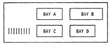 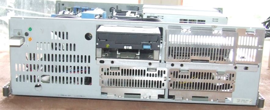 DASD Storage Matrix - PS/2 Model 90 (Not complete, confusing)
* - 3.5” Device Filler Bezel takes up extra room to the right for shorter device bezels. ? - Not sure at present. I do not have a FRU for an A bay Ground Shield, however, there is a single slot in the drive support shelf, similar to the B bay. The Ground Shields for the B: bay [5.25"] are NOT compatible with those for the C: and D: bays. The Ground Shields for the B: bay [85F0006 / 85F0005] use a sorta "cage", where the shield has depth, plus the lower hooks actually extend into the frame and hook into slots. The C: and D: bay Ground Shields [85F0034] are flat and they slide over the sheet metal lip at the front lower frame edge. The Hard Drive Slide fits in B [leftmost pair of "lips"], C bay [duh] and D bay. If you are trying to deal with mounting a SCSI hard drive in C bay and the DBA-ESDI sockets are present, consider putting the SCSI HD in B bay. The Hard Drive Slide does NOT fully seat in the A bay, and about 1/3rd of the hard drive sticks out of the frame... NOTE: If you try stacking two drive slides together in order to allow the hard drive SCSI connector to clear a DBA-ESDI connector, the hard drive will be close to the top of the frame opening [reducing airflow around drive enclosure]. The kicker is that the bottom of the SCSI cable connector is now very close to the upper forward edge of the DBA-ESDI connector. The 3.5” Device Filler Bezel works in the B bay and D bay. It isn't flat like the other D bay bezels, but it fits and works. The 1.44 / 2.88 Floppy Bezel works in A bay, B bay [with device filler bezel] and also in D bay [with device filler bezel]. Electromagnetic Shield Bays A and B EMS 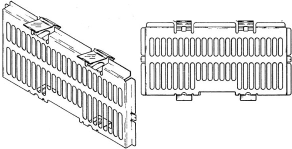 At least one of the upper bay shield members has extension or boxed portions folded backward from the front face of the shield in such a way as to form extensions and provide a certain depth to the shield. Bay C and D EMS 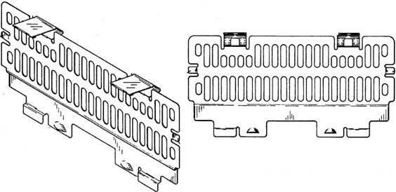 US5191544A Personal computer enclosure with shielding J5 - Base Fan Two access holes through the Model 90 Base Frame to allow for the removal of the Base Fan 64F4128 WITHOUT having to remove the Adapter Card-Guide Assembly 33F8363.  If you will notice the two diagonally spaced round holes... The upper right hole fits the fan mounting screw perfectly. The lower left round hole does NOT line up with anything. If you use the widened rectangular hole just above it and to the right, that lines up with the lower fan mounting screw. SWAG: At one time, IBM considered using a 120mm fan, and these are the original access holes. For whatever reason [noise, lower than expected heat levels, cost] IBM wendt with a 92mm fan. After deciding to go smaller, the easiest thing to do was to open up the grille to allow access to the fan mounting screw. Just noticed something, the speaker is only about 3/16" in front of the fan opening... Another item, the fan is darned near impossible to touch, as it is behind the grille in the frame -AND- it is mounted to the card guide. So why IBM felt it needed a front and rear finger guard, I dinna ken. However, SIMMply dropping both the front and rear finger guards leaves the mounting screws about 1/8" from seating... Fan With Finger Guards Removed and Speaker Laying on Frame 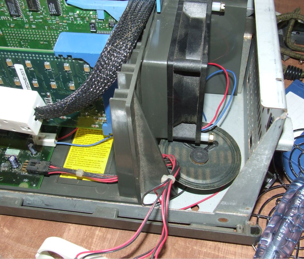 To remove fan, you need to drop the power switch / speaker frame, use a 3/16" nutdriver to remove the single black mounting screw to the upper right of the power switch. Pull the frame slightly rearward to clear the switch's white button. Now you have room to remove the base fan. Use a 3/16" nutdriver on black screws, 1/4" nutdriver on gold screws (some 90s use larger head screws]. There are holes on the front of the frame that allow you to access the fan mounting screws. Unscrew both mounting screws, drop fan, pull both finger guards off, pull the white nylon screw spacer from under each mounting screw head. Use two nylon spacers 1/4" long, for #6 screws. Push both mounting screws back into the fan frame, remount the fan [the model sticker faces IN]. Pop the speaker from it's mount, place speaker on floor of frame. It fits under the fan, BTW... Base Fan Particulars Panaflo DC Brushless 0128A0-Z Model FBK-08A12L DC12V 0.09A Matsushita Electric Japan size Power Air flow Air pressure Noise Model ------- ----- -------- ------------ ------- ---------- 80x25mm 0.66W 22.6 CFM 1.8 mmH2O 23 dB-A FBK-08A12L FBK-08A12L Motor Type FB: Panaflo (DC Axial-flow fan) Bearing Type K: Ball Bearing Housing Size 08: 80 x 80mm Housing Thickness A: 25.5mm Rated Voltage 12: 12 VDC Speed L: Low - Maybe 1900 RPM Solid Corners Base Fan Connector KK 3.96mm Crimp Terminal Housing, Friction Ramp, 2 Circuits https://www.molex.com/webdocs/datasheets/pdf/en-us/0009508023_CRIMP_HOUSINGS.pdf Base fan uses AWM Style 1007, 24 AWG wire. Use With KK 3.96 Crimp Terminals, 2478 , 2578 , 6838, 7258 , 45570 Model 90 Power Switch Positions  Push In, Button stays recessed - On Push Again, Button extended - Off Power Switch 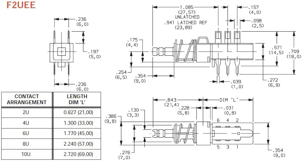 Schadow 221, F2UEE is closest. Remove Cover 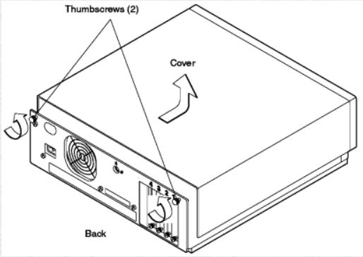 IBM says: Loosen both thumbscrews on back panel. Remove cover by sliding it forward approximately 50 mm (2 in.), and then lifting it. Reverse procedure to replace cover. My way - Loosen both thumbscrews on back panel. Do NOT remove them, they are captive. Remove cover by slapping it on the sides with the palms and fingers of both hands, thumbs on the top of the case -AND- pushing / pulling it foreward. Slide it forward @ 2 in., and then lift it. Sometimes it takes more moxie to start the cover. Reverse procedure to replace cover by SIMMply placing the horizontal pins into the rails, then slowly push the top cover rearward until it seats.. Model 90 Trim Strips US5420760A Microcomputer enclosure with interrupted wedge locking arrangement and shielding liner 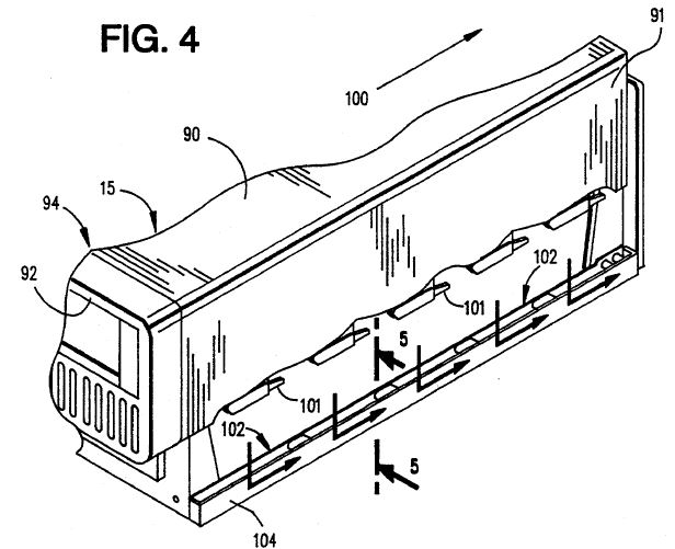
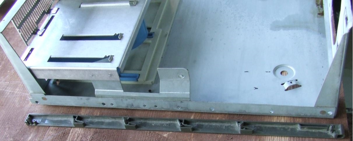 Mounting Model 90 Trim Strip 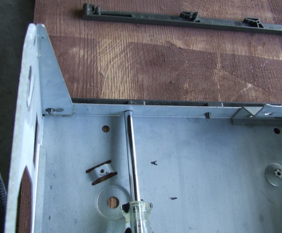 There are two mirror image Trim Strips. One is for the left side, the other is for the right side. In order to pull them [or attach them], you need to pull the PSU and pull the planar. They are fastened in with four split posts and two small plastics screws [3/16th nutdriver] 85F0030 - trim strip on Slot 1 side 85F0031 - trim strip on PSU side Adapter Card-Guide Assembly 33F8363 US5136465 PC with Tandem Air Flow Dual Fans And Baffle Directed Air Cooling 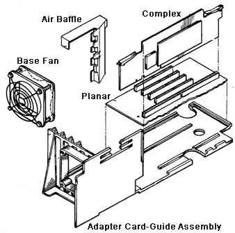 In order to remove the Card Guide, you have to remove the PSU, take all adapters and memory risers and cables off the planar, then remove the planar screws, pull the front edge of the planar up [pivoting on rear ports], them remove the card guide mounting screws. Easy-peasy... Why was the 90
introduced? DBA-ESDI Boot Support with the Type
0: Daniel Hamilton dug down into the
Type-0 abyss and found out while yes you can boot from
the DBA-ESDI drive, you must still have a SCSI drive on
a Spock to provide IML. Read his further bone-chilling
adventures in the DBA-ESDI Temple of Doom HERE
Being able to boot from a DBA-ESDI drive as C: offers a
simple upgrade path for the Model 70 to Model 90, just
by swapping the drive out. One advantage the model 90 has over the 77 is the 8 SIMM slots. Eight 8MB SIMMs are allot cheaper than four 16MB sticks right now. We also have the caching SCSI that could have its cache upgraded. You don't have to pull adapter cards to reconfigure RAM. I prefer the planar mounted bus connectors too. From Us, the god-Emperor of Micro Channel: After many years of dabbling in Processor Complexi, I find the Model 90 (8590 or 9590) to be THE preferred complex based system to experiment with complexi and / or memory. The 95 is still my heartbeat, but consider: Complex Seating - The Model 90 orients the complex vertically, so you can press down on the center top edge of a complex to seat it. The 95 forces you to drop it down on it's side if you want to firmly seat the complex, or try to hold the complex with one hand, center the complex in the double long socket, and press it in while bracing the system with your other hand. NOTE: From sad personal experience, on a 95 standing up, the complex can hang down below the complex double slot if you don't pull the blue levers stick straight up from the planar before trying to seat the complex. Then carefully place the complex edge connector in the complex slot. Push the complex in until it seats and the fingers on the blue latches are lined up with the case supports. You may have to push one end of the complex in and then the other. If you cheat and use the blue levers alone to seat it in a Model 95 without firmly seating the edge connector in the slot, you CAN shear off some surface mount components from the lower back side. Changing Memory - The Model 90's memory is on removable cards, to change memory, you pop the cover off, remove the riser bracket, and pull the risers. On the Model 95, you have to pop the front bezel, pull off the side wall, pull the AC plug out of the back, loosen the PSU, drop the PSU, change the memory, then push any cables out of the way before putting things back together... Where the 95 edges out the 90 is drive bays and better work area. The 90 has a peculiar floppy cable, and when you add a ribbon SCSI cable, things tend to get jumbled between the corner of the drive support shelf and the PSU support bracket. Using a flexible sheathed cable like in the 957x series or the 95's F/W cables, it becomes much easier. I would like to see a round single floppy cable for the 90. That would really help eliminate the cable confusion.... Actually, the 95 could benefit from a round single floppy cable as well. I usually stuff the unneeded floppy connectors in the B: area. But that makes seating a full length card in Slot 3 a struggle. Mounting a CD ROM in a 90 depends on having the correct width drive sled and finding the uncommon CD Rom bezel. Whatever. If you think of it, a 90 is a fun box for the experienced user. Model 90 Mockup (?) 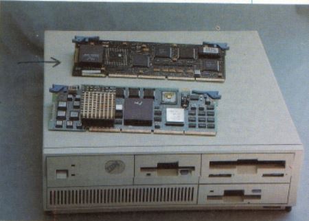 This is an image snagged from UMMR, from an ad for a complex update for the 90 / 95. Of particular note is the Bay D bezel in the lower right. Might make a decent cover for a SCSI2SD adapter.... "Model" 90 A Model 90 is a system for a more experienced individual. Not that it is any more difficult than a 95 to configure, but you have to accept it has four slots and XGA on the planar. Thanks to UZnal, we now have True Color support for the XGA under Win9x AND protected mode support for the IBM SCSI adapters running on Pentium systems. 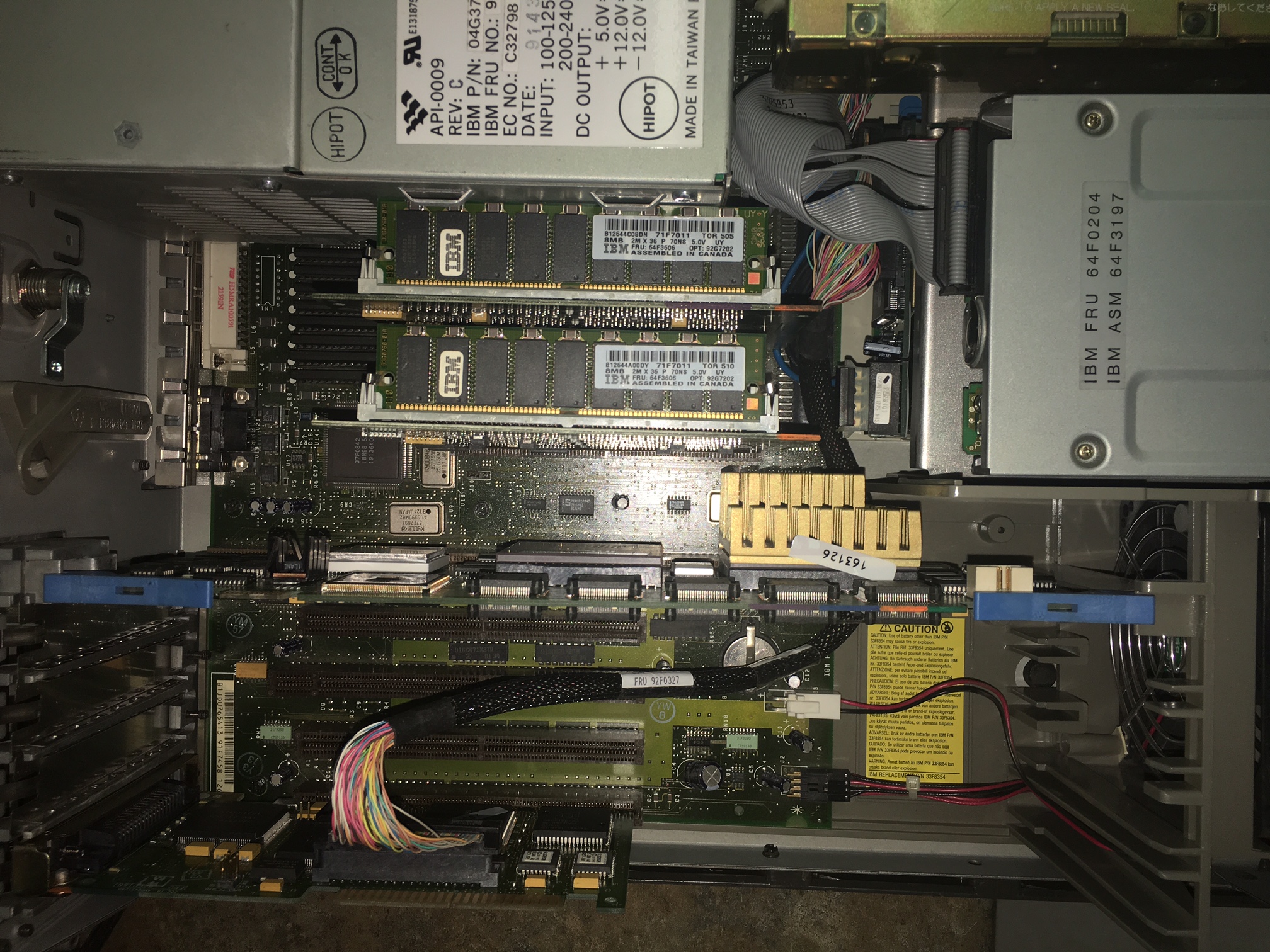 Look at this ode to simplicity! The 50 pin flat cable is gone, making servicing the RAM risers _SO_ very much simpler. Do you see how the cable runs to the front, then under the adapters? Using a SCSI cable that is long enough is crucial here, as short cables force one to place the SCSI card closer to the complex, and forcing you to run the cable over the complex or under the complex and barely reach the drives. NOTE: I always wondered why the P60 and P66 complexi heatsinks were milled in that odd step fashion. Look how it clears the adapter card bracket... CDROM Attachment 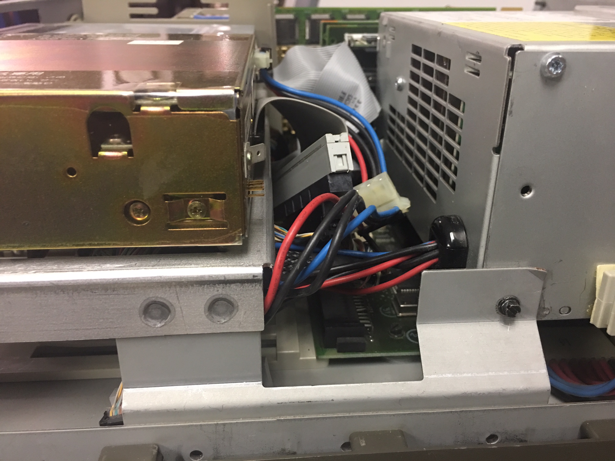 Look at the cramped space available for hooking up the CDROM. What is difficult to see here is the thoughtful SCSI cabling. The F/W cable goes up to a 68 to 50 pin adapter. Now the space saver is the short length of 50 pin flat SCSI cable (white socket) running from the 68 to 50 pin adapter to end in the SCSI CDROM. The F/W cable then ends with an active terminator. 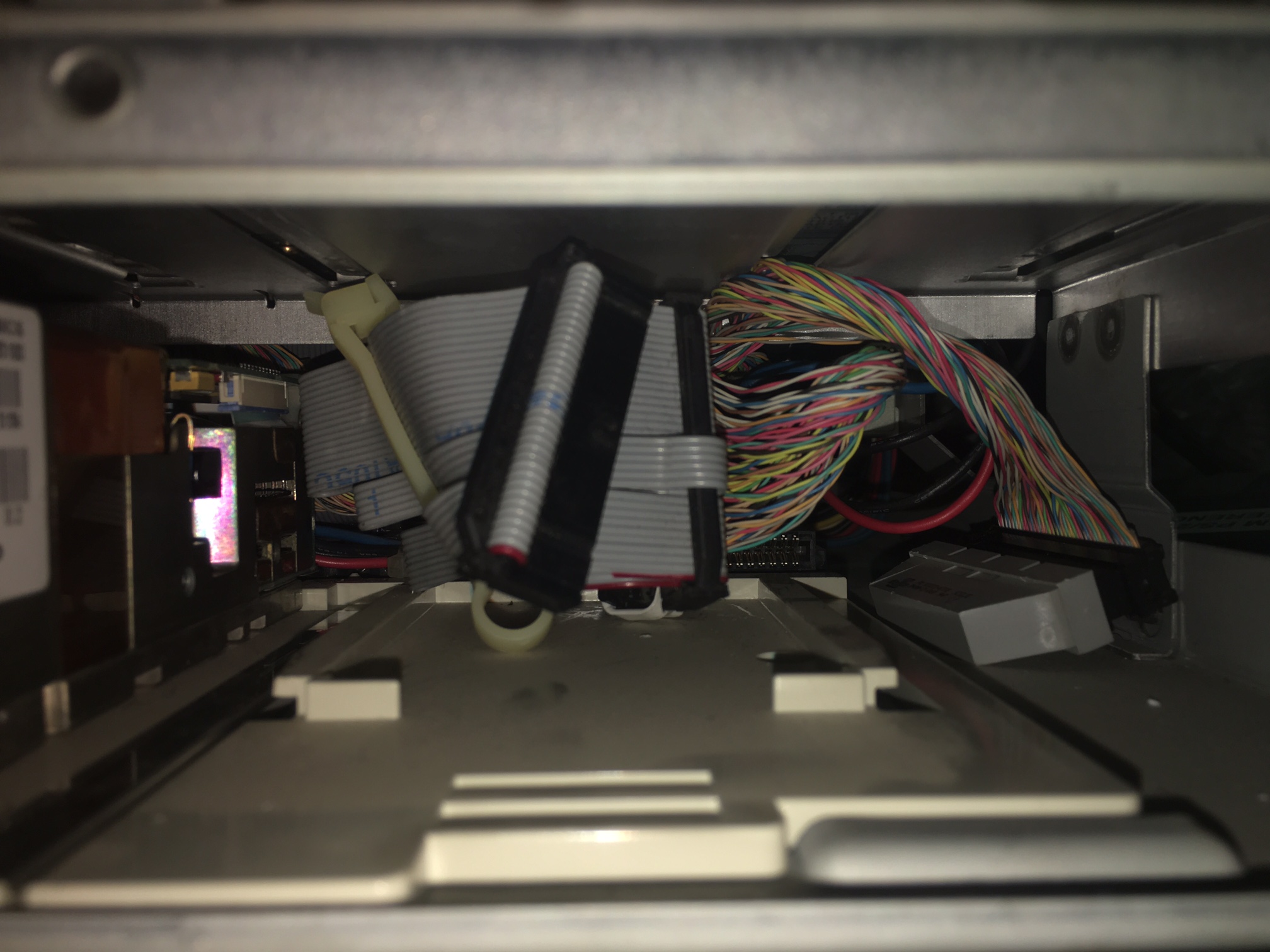 Trying to insert a 68 to 50 pin adapter in the CDROM, then plug in a F/W HPDB68 plug into that crams the SCSI cable up against the front of the PSU. Fast/Wide to 50 Pin SCSI Wide to Narrow Adapters DM5000-5068-02 I was in deep Super High Intensity Tinkering with a Model 90. Trying to hook up a 50 pin SCSI device to a F/W cable, and as many of you have experienced, there ain't much room, especially if you are trying to have a 50 pin stub cable.... What would make life easier is a Wide to Narrow adapter, Female to Female. These plug INSIDE the 50 pin MALE connector on the SCSI device and the wide 68 pin MALE plug on the F/W cable fits OVER the FEMALE wide plug. Remember to have a wide device [SCSI drive -OR- active terminator] AFTER the narrow device to terminate the SCSI bus. NOTE: I personally wandt a real wide terminator device after the narrow device. Methode made the Datamate line of SCSI cable adapters, and one appears to be what the doctor ordered and why the preacher danced. DM5000-5068-02 = Universal Feed Thru with Capacitors on High Lines Optional capacitors (10pf) are used in adapters on the additional 9 high signal lines when going from a wide controller to a narrow device to balance the loading to all signal lines. Does not terminate, so you need a device that can terminate at the end of the F/W cable [either a SCSI drive or an active terminator]. NOTE: Be careful, some DM adapters are for differential! Alternative - No Internal CDROM 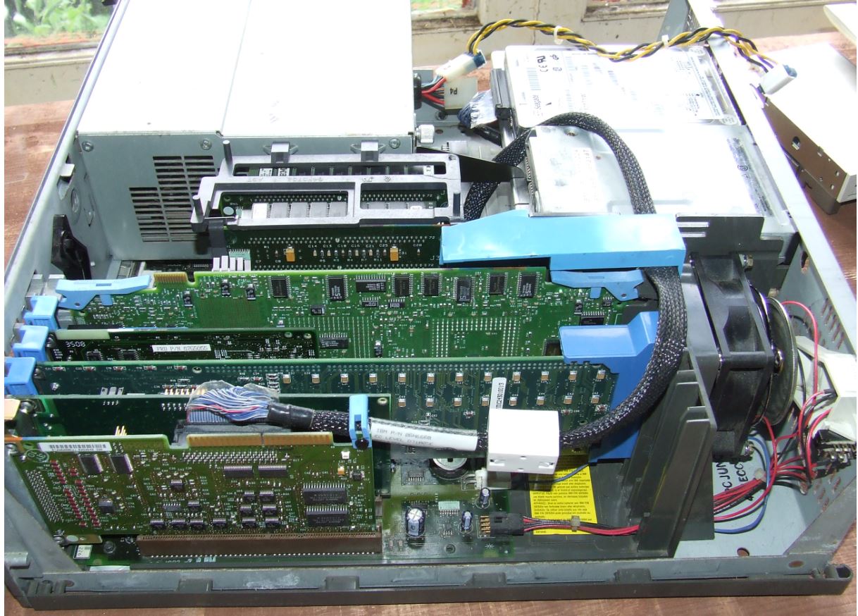 I attained a higher understanding of the blue mysteries when I decided to run an external CDROM. Take the SCSI HD out of C Bay and SIMMply stick it in B bay. Enable termination so it can be the last device on the SCSI bus. The only clutter is the original floppy cable. I'll still use the original cable while grabbing some round clone floppy cables. Top Routing of SCSI Cable 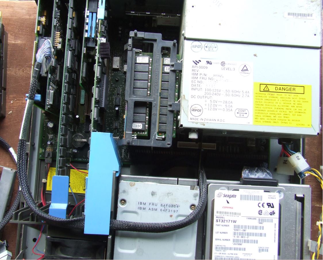 See the SCSI cable on top? Plenty of room under the blue air baffle. I tried sliding the HD into A bay, but the HD slide only goes in about 2/3ds of the way, then STOPS. The floppy slide's mounting holes are spaced differently than the HD slide. The single device F/W cable is 06H6660. Mounting Model 90 Vertically Vertical mounting of the PS/2 Model 9590 requires an appropriate fixture. The Model 90 left side vents point downward, with a minimum of one inch (25.4mm) between the vents and the supporting fixture. J16 and J23 Artifact-
IBM brought out a "low-end" Mod. 90 with DBA-ESDI and a
386DX-20 processor board. (Ed.
A big insurance company (Aetna?) had 386DX-20 complexes
made for it- the "Type
0"). NOTE: Apparently,
so did Royal Bank... The Model 90 supports three diskette drives through the type 2 diskette controller. A cable with three diskette drive connectors (pin format not berg or edge connector) attaches directly to the planar. In an environment with two or three diskette drives installed, the specific connector that the diskette drive connects to determines its physical drive number. This is important in a selectable boot environment. All connectors support all diskette devices listed above, in any combination. The connector layout is different in the Model 90 and Model 95 systems: Diskette Drive Signal Cable FRU 57F3030 -or- P/N 33F9953 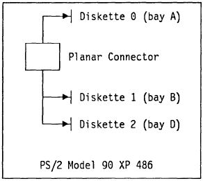 Adapting
Clone
Cable to 40 Pin Port I don't know what happens if you miswire or swap
orientation of the plugs. But you are placing signals
where they weren't designed to go. YMMV. Adapting a 34-pin Cable
Pull wires 10-16 (the ones you slit), and
twist them 180 degrees [sets this floppy to A:]. Align
the lower 9 wires, the twisted 7 wires, and the
remaining wires through the 40 pin plug. Crimp. Trim
excess with X-Acto knife or similar. Done. The original Model 90 HD slide, 64F4863, fits C: and
D:... There may be an earlier drive slide, 54592-001,
Watson Code C-1961. The 54592 is about the same, except
the lifting tab has square edges at the tip, while the
64F4863 lifting tab has a beveled edge at the tip.... 61X8724 is the same length from latch to rear of 64F4863 slide, but the sides are about .25" longer to the front. Fits great, the cut-outs in the EMC bezel are not really needed. 64F4863 (Top) and 71G7506
(Bottom) 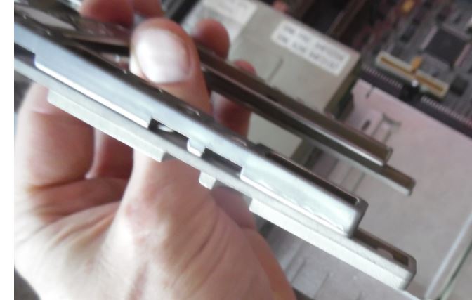 The 76/77 drive slide, 71G5706 (71F3300 appears to be earlier version) will not fit in C: (too long, plus catch is about .1 too long), BUT... BUT... if you slide the 76/77 slide into the D: bay, you will notice the frame recess is longer AND there are two sets of recesses for the catch at the front. Fits fine. 71G5706 left (D drive), 64F4863 right (C drive) 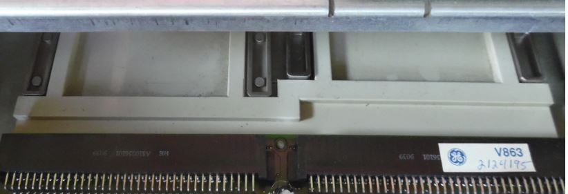 C drive bay left, D drive bay right 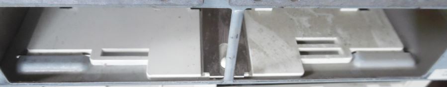 Now why did IBM do THAT? Two sets of drive retainer
slots? Using a 71G5706 in D
Bay 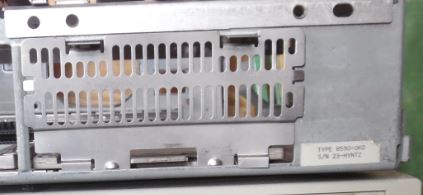 I seated a 71G5706. While the catch does not engage, it is a firm grip anyways, the EMC bezel is cut out at the corners AND has a cutout at the center where the longer catch fits snugly. For those new to PS/2s, such a combination would seem miraculous, but I'd rather chalk it up to a pragmatic decision. If the slide remains the same, then alter the EMC bezel...
Calculate Hard Drive Mounting
Screw Length for Model 90 If you ever loose your Model 90 Hard Drive mounting
screws, here's some facts: The Model 90 Hard Drive Slide has recessed screw
pockets. So, let's calculate the MAXIMUM screw length for a HD
mounting screw in a Model 90. [ed. 3/8" screws
work just fine] 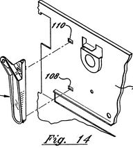
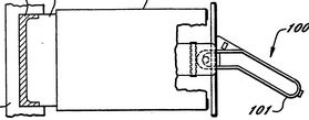
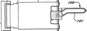
US5325264A Device for removing a direct access storage device from a personal computer This patent is for a plastic tool that pivots on the 90 plastic drive frame, hooks under the "lip" of the DBA-ESDI sled, and lifts the tab up and pulls the edgecard out of the planar socket... So... that little plastic tool hanging off the inner rear wall of the Model 90 is specifically for a DBA-ESDI drive. They would normally NOT be supplied with a SCSI based system. How to Remove HD Removal Tool The tool has a set of barbed teeth at the top, which fit into "107". There is a hook which slides into "108". Pry the top out from the case and rotate the top of the tool forward, once the top is free, pull up and out.
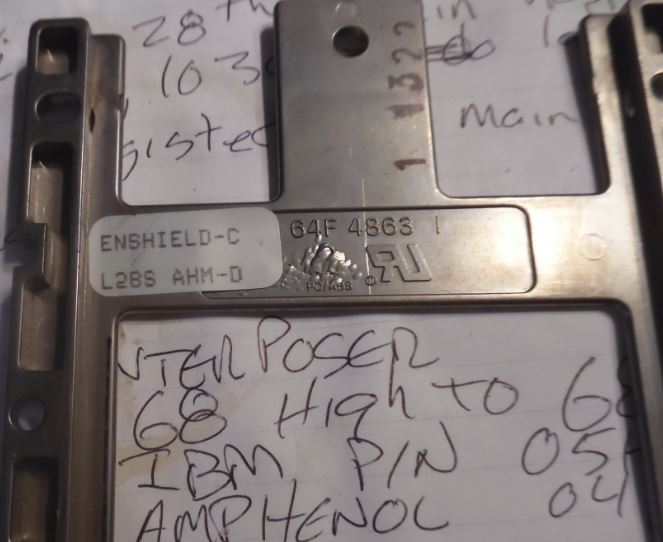
Fitting Model 90 Planar over Rear Wall Port 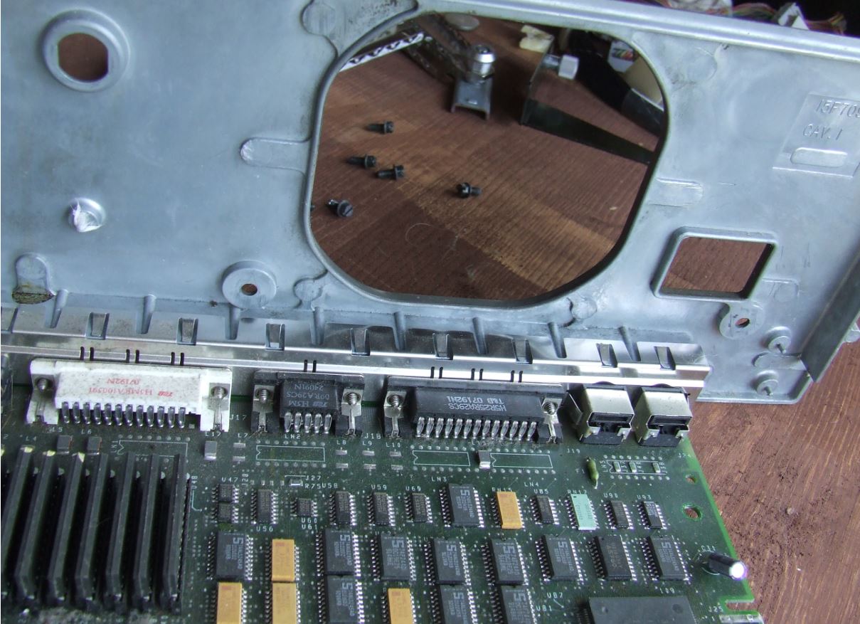 If you are replacing a planar, the EMC bezel on the ports section fits OVER the top and UNDER the bottom of the well in the cast aluminum rear wall. See the cast-in aluminum fins, and the slits in the EMC bezel? EMC Bezel Fit Over Ports Well US5353202A PC with shielding of input/output signals 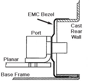 Model 90 Drive Slide Conductive Coating While digging for some AMP F/W connectors and
Specta-Strip SCSI cable, I foundt another Model 90 hard
drive sled, 64F4863. Again, another sticker saying
"ENSHIELD-C". So I wendt looking and sha-zaam! Three
Floppy
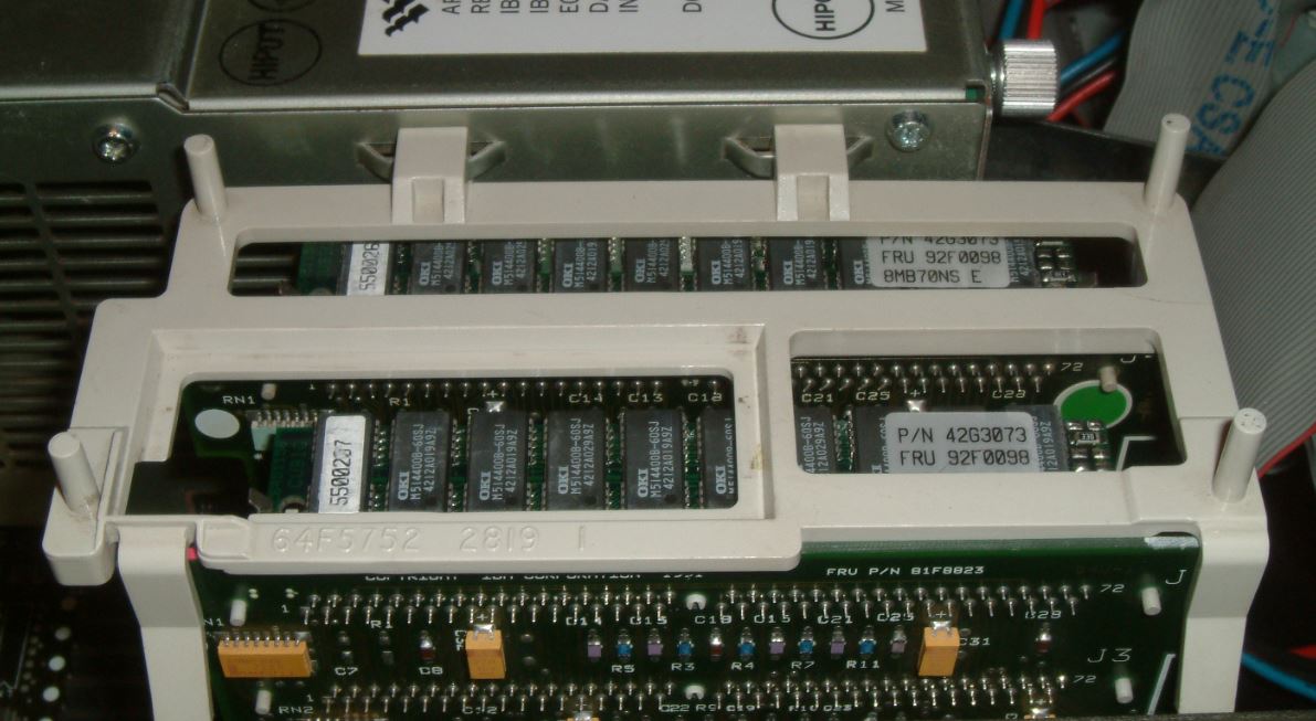
Experience Memory Riser  Memory Riser Card Support Bracket
Further Super High Intensity Tinkering with the Memory
Riser Bracket show it does two basic functions first,
retain the memory risers in the planar sockets, second,
provide a space for the SCSI EMI filter. The retaining function covers keeping the risers down
in the sockets via the bracket's fit against the
underside of the cover. The other part is keeping the
top of the risers from rocking back and forth between
the complex and PSU. 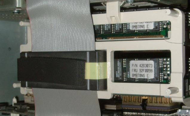 Memory Riser Position
White Memory Riser Bracket
64F5752 Jelte shows us there's still some variations in the
Flux Capacitor...
|