Opto22 is one of the rarest companies, they made microchannel
adapters which still work with current production components... As
with anything from the mythical PS/2 era, you have to know WHAT
works with WHAT in order to find usable stuff on flea-buy...
First, there are two main communications styles, Optomux,
RS-422/485, using a DB9 serial port, and Pamux, using a 50 pin flat
cable. You cannot directly hook one to the other. You have analog
and digital I/O modules, which CANNOT be mixed on the same rack.
Finally, the racks power requirements vary.
The AC32 and AC34 -DO- support the PB16HQ Quad I/O modules.
Now comes the Brainboards. B1, B2, B100, B200, E1, E2, and B3000
Brainboards are Optomux compatible. The E1 and E2 Brainboards have
an Ethernet port and a RS-422/485 port, but the AC32 / AC34 lack
Ethernet.
Research
826 Opto 22 Product Guide (October 1996).
odtkR12a.exe
OptoDriver Toolkit for mistic I/O and Optomux Compatibility: Win95, 98, ME, NT, 2k (SP4),
WinXP Pro (32-bit SP2)
The
OptoDriver Toolkit for mistic I/O and Optomux contains the drivers
and documentation necessary for direct communication between
application programs running on a PC and Opto 22 mistic and Optomux
I/O systems. Applications can be developed using languages such as
Microsoft C++ or Microsoft Visual Basic.
NOTE for Optomux users: The
OptoDriver Toolkit does not support Ethernet-based brains and does
not support communication over Ethernet with E1 and E2 brains.
Although you can use this toolkit for serial Optomux communications
with E1, E2, B1, B2, and serial B3000 brains, a newer toolkit that
handles both serial and Ethernet Optomux is preferable for Windows
2000/XP systems: Optomux Protocol drivers and utilities. The Opto
Driver Toolkit is useful, however, for those who have an existing
Optomux application based on an older version of the OptoMWD driver
for Windows 32-bit or Windows 16-bit systems.
IMPORTANT: The OptoDriver
Toolkit is available free of charge. To install it, however, you
must supply this password: 12DROWSY98
0882
OptoDriver Toolkit for Custom PC-based Control Data Sheet 1165
PC-Based I/O Overview
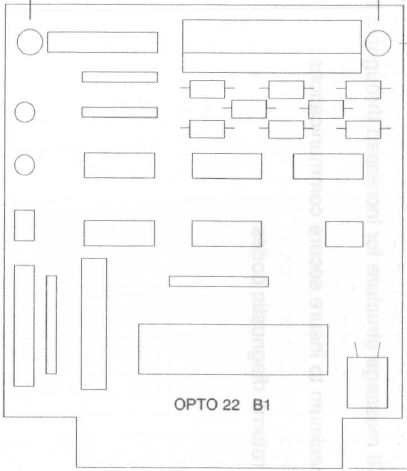
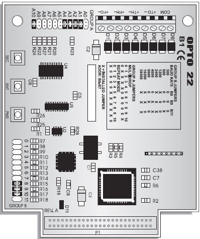
B1 and B2 Brain
Boards (Optomux)
Old B1 -
001828
New B1 - 007308
0463
Optomux 16-Channel Digital (B1) and Analog (B2) Brain Boards Data
Sheet
0464 B2 Analog Brain Board Data Sheet 1574
B1 and B2 User's Guide 2113
B1 and B2 Jumpers in-the-box 0203
OPTOMUX Protocol User's Guide 0524
Optomux and Optomux Support Products Data Book 0092
Optoware Manual - replaced by Opto 22 1572, the Optomux Protocol
Guide.
KB83808
Response times
The B1 and B2 boot up in about 1 second.
The E1 and E2 boot up in about 7 seconds.
B1
Compatible I/O and mounting racks:
- G4 digital I/O: G4PB8H, G4PB16H, G4PB16HC
- Integral G4 I/O: G4PB16J, G4PB16K, G4PB16L
- G1 digital I/O: PB4H, PB8H, PB16H, PB16HC
- Integral G1 I/O: PB16J, PB16K, PB16L
- Quad Pak I/O: PB16HQ
B4, B5, and B6 Brain Board (Pamux) 0737 B4
Installation Notes - 32-Channel Digital Brain Pamux (B4 is 001788) 0127
(Older) Pamux B4 Manual, Revision K and Lower 0738 B5
Installation Notes - 16-Channel Digital Brain Pamux (B5 is 001830) 0739 B6 Data
Sheet - 16-Channel Analog Brain Pamux 0726 Pamux User’s Guide
2006 0726 Pamux User’s
Guide 1996 TERM1
Pamux bus Terminator card TERM2
Pamux Bus Termination Card Shielded Cable
NOTE: The
final Pamux brain board on the bus must be terminated with a TERM1
or TERM2 terminator board. A TERM2 board is identical to the TERM1
in size and function. The only difference between the boards is
that the TERM2 offers lower line impedance than the TERM1. This
may prove useful when using a cable that differs from recommended
specifications.
B5
Compatible I/O and mounting racks:
- G4 digital I/O: G4PB8H, G4PB16H, G4PB16HC
- Integral G4 I/O: G4PB16J, G4PB16K, G4PB16L, G4PB32H
- G1 digital I/O: PB4H, PB8H, PB16H, PB16HC
- Integral G1 I/O: PB16J, PB16K, PB16L
- Quad Pak I/O: PB16HQ
B100 and B200 Brain Board (mistic /
Optomux)
0729
B100 Data Sheet - 16-Channel Digital Brain, Mistic/Optomux Protocol 0730
B200 Data Sheet - 16-Channel Analog Brain, Mistic/Optomux Protocol
B3000 Brain Board (mistic / Optomux) 0787
B3000 SNAP Analog/Digital Mistic/Optomux Brain Data Sheet NOTE: If B3000 is jumpered for
Optomux protocol, it acts as two B1 digital brain boards and two B2
analog brain boards. NOTE:
B3000-B does not support the Optomux protocol !!! 1794
B3000-B-OMUX uses the Optomux protocol! There is a
sticker on it.
The B3000 or B3000-B can be used as an independent processor.
The brain’s built-in event-reaction capability essentially makes the
B3000 or B3000-B into a simple-state machine, with some expanded
“time-based-state” capability provided by counters and frequency
inputs, as well as analog input levels.
B3000 Flash Firmware
If you have a B3000 brain that was manufactured after July 1998,
your firmware can only be updated with a hardware upgrade. Older
B3000 brains can be updated using special software.
SNAP I/O racks come in three model types: D-series (direct, digital only), B-series (for brains,
digital and analog), and
N-series (for brains plus remote communication adapters). All SNAP
racks use a single 5-volt power source and feature standard panel
mounting or DIN rail mounting.
D Series racks use the same 50-pin
connector as Opto 22 Classic racks and are therefore compatible
with Opto 22 Classic brain boards. B Series racks are designed for integration with SNAP I/O
processors (brain boards) and allow a combination of analog and
digital modules on the same rack.
0784
SNAP B-Series Racks Data Sheet Supports a mix of Digital and Analog
modules with B3000 0785
SNAP I/O Mounting Racks: B Series - Terminal Strip Data Sheet 1776 SNAP I/O Mounting Racks: D Series and B Series 0788
SNAP Component List 0796
SNAP Racks Assembly Instructions 1403
SNAP I/O Wiring Guide 1120
SNAP Power Supplies Data Sheet 0953 SNAP Loop
Power Supply Data Sheet SNAP-PS24 and SNAP-PSDIN
E1 and E2 Brain Board (Optomux and
Ethernet) 1546
E1 and E2 Brain Board Data Sheet 1563 E1
and E2 User's Guide 1576
I/O Configuration for E1 and E2 Brain Boards 1567
E1 and E2 Architecture and Migration Overview 1581
Using E1 and E2 Brain Boards for Ethernet-to-Serial Routing 1579
E1 and E2 Product Overview RM_E1_E2_FW E1 and
E2 Firmware README
Application Notes TN9601
Applying Dry Contact Output Modules TN9602
Power Supplies for Optomux and Pamux Systems TN9604
Applying Transformer-Isolated Analog Modules TN9603B
Operational Interference and Noise TN9603C
Interference Generation and Compatibility TN9604
Applying Transformer-Isolated Analog Modules
1104
Guide to Troubleshooting Legacy Opto 22 Products Opto_LegacyProducts.zip Opto
22 legacy products for Visio 2003 (mistic controllers and I/O, E1s,
E2s, and G1 and G4 I/O modules) Opto_Hmi_and_MiscIcons_v2.vss
Opto 22 Visio Stencil Library of HMI Images( pumps, valves,
compressors, tanks, gauges, etc.) Mounting Racks
NOTE: I/O racks without the “H”
suffix may not have the correct on connections to supply power to
the brain board. These non "H" racks are probably in the G4 and Quad
Module racks.
0479
PB16HQ Quad 4-Module Position Rack (16 channel) Data Sheet
Optomux, Pamux, and Mistic protocol brain boards 1271
Using Power Supplies with Opto 22 Systems
0490 Classic Accessories -
Cables 1120 SNAP
Power Supplies
0491 PBSA
(120v), PBSB (220v), and PBSC (12/24v) 5v DC power supplies
Module
Part Numbering
IDC - DC input - White
IAC - AC input - Yellow
ODC - DC output - Red
OAC - AC output - Black
LC4
0108
Optomux and Local Controller Programming Notes
Apps
and programs for LC2 / LC4 controllers. Programs are IBM PC BASIC or
FORTH 83, resident languages on LC2/LC4.
Snippet: Rev A LC4 have "Address" jumpers and no 4th jumper.
LC4 supports 27256 (32KB) and 27512 (64KB) EPROM.
AUTO Jumper - Auto-Boot upon power-up when jumpered.
EPROM chip (model no: L4P2xx) provided by Paragon to run control
blocks that come with standard functions.
LC4 can be programmed in BASIC, FORTH, or PARAGON LC
0466
AC7 RS232 to RS422 Converter (AC7 is 12v DC) 0233 AC7A -
AC7B Users Guide RS232-RS422/485 Converter (AC7A is 120v, AC7B is
220v) 0960
AC7A/B Adapter Card Data Sheet RS232-RS422/485 Converter (AC7A
is 120v, AC7B is 220v) Forth-83 Books
Starting
Forth: An Introduction to the Forth Language and Operating
System for Beginners and Professionals, 2nd Ed. 1987
By Leo Brodie ISBN-10: 0138430799 ISBN-13: 978-0138430795
Thinking
Forth: A Language and Philosophy for Solving Problems, 1984
By Leo Brodie ISBN 10: 0139175768 ISBN 13: 9780139175763
Mastering
Forth 2nd Ed, 1989 by Martin Tracy and Anita Anderson ISBN-10: 0135599571 ISBN-13: 978-0135599570
LC
COMMUNICATOR
0494 Hand-Held Terminal for Optomux part
number: LC COMMUNICATOR. LCTERM Version 1.35 - Simple
terminal program that communicates with LC4 and LC2 controllers. 227.0
LC Communicator User Manual
Cyrano Opto-22 Forth for a
proprietary embedded controller. Cyrano runs on Pamux.... 0702 Cyrano
User's Guide 0703
Cyrano Command Reference 0704 Cyrano Tutorial
PamScan R3.0a DOS utilities
for troubleshooting Pamux hardware. uh oh, I see AC28 in the Help
file...
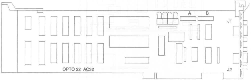
AC32 Dual RS-422/485 Adapter For Micro
Channel Computers
The AC32 is a dual RS-422/485 adapter card (transient protected) and
features two independent asynchronous channels (each able to drive
up to 100 devices on a multidrop network). Channel A can be selected
for COM1 through COM8 and channel B can be selected for COM2 through
COM8. The AC32 offers full hardware and software compatibility with
IBM PS/2 Models 50, 60, 70, 80, and compatible computers. The AC32
operates as a full duplex device with transmission speeds up to
38,400 baud for distances up to 5,000 feet using two twisted pairs
per channel and a ground.
J1 (A) - DB9
J2 (B) - DB9
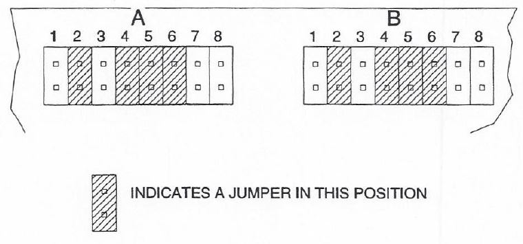
AC32 Jumpers
Each port is configured on the adapter by a group of 8 jumpers. Both
Bank 'A" and "B" jumpers share the same function.
Position
Description
1
Pull up jumper for transmit line
2
Terminate jumper for transmit line
3
Pull down jumper for transmit line
4
Terminate jumper for receive line
5
Pull down jumper for receive line
6
Pull up jumper for receive line
7
Enables RS-422/485 driver from RTS
output on UART
8
Not used
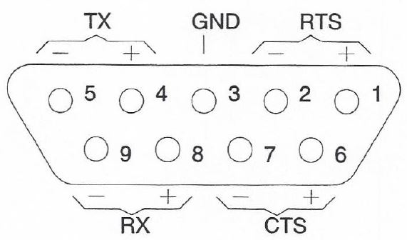
Serial Port Pinout
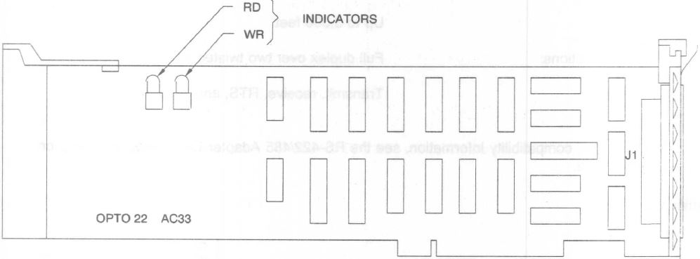
AC33 PAMUX Bus Adapter For Micro Channel
Computers
The AC33 interfaces to a PAMUX network. Each AC33 can drive up to
512 digital I/O points, 512 analog I/O points, or a combination
thereof over a total distance of 500 feet.
J1 - 50 pin male header.
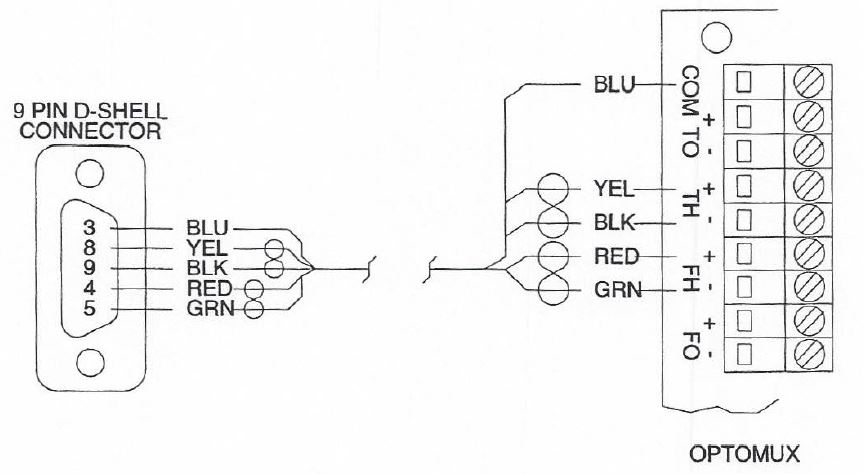
Connecting Wire
This is the wiring between the D shell connector
and the first OPTOMUX on the link.
Please note that the pin numbers are labeled on the connector.
Communicating With
OPTOMUX
Before applying power to OPTOMUX Brain Board(s), set the
baud rate and command protocol on the OPTOMUX Brain Board(s).The baud rate and
command protocol are selected by the B group of jumpers on the
OPTOMUX Brain Board(s). (Please refer to the OPTOMUX B1 and B2
Digital and Analog Brain Boards Operations Manual, Form 203 for
additional information.)
For the checkout, remove all of the group B
jumpers from one OPTOMUX Brain Board and disconnect all other
OPTOMUX Brain Boards on the network. This will select a baud rate
of 300, the four-pass protocol, and an OPTOMUX address of 255.
Connect the D shell connector to the AC34 card
and turn on the power to the IBM PS/2 and the OPTOMUX.To test the link, enter
the IBM BASIC interpreter and type in the following program. The
underlined part of line ten must be changed to COM1 when using the
AC34 card as communications port one.
10OPEN "COM2:300,N,8,1,RS,CS,CD,DS" AS #1
20PRINT #1,°>FFACD"
30INPUT #1,B$
40PRINT B$
When running the program, both the receive and
transmit LED's on the OPTOMUX will flash. The IBM PS/2 will
display the AFFACD on the screen. If nothing is displayed, verify
that all the wiring has been done correctly.